Electronic photographing device for panoramic photographing and editing

a technology of panoramic photography and electronic photographing, which is applied in the field of electronic photographing devices, can solve the problems of cumbersome operation and the inability of the printer to be directly operated by the camera, and achieve the effect of reducing the number of cameras

Inactive Publication Date: 2003-12-09
XACTI CORP
View PDF17 Cites 30 Cited by
  • Summary
  • Abstract
  • Description
  • Claims
  • Application Information

AI Technical Summary

Problems solved by technology

When the image data corresponding to the panoramic image photographed in the panoramic mode is stored in an external memory device, the following cumbersome operation is required.
Additionally

Method used


Image

  • Electronic photographing device for panoramic photographing and editing
  • Electronic photographing device for panoramic photographing and editing
  • Electronic photographing device for panoramic photographing and editing

Examples


first embodiment

The operation of the first embodiment will be described below.

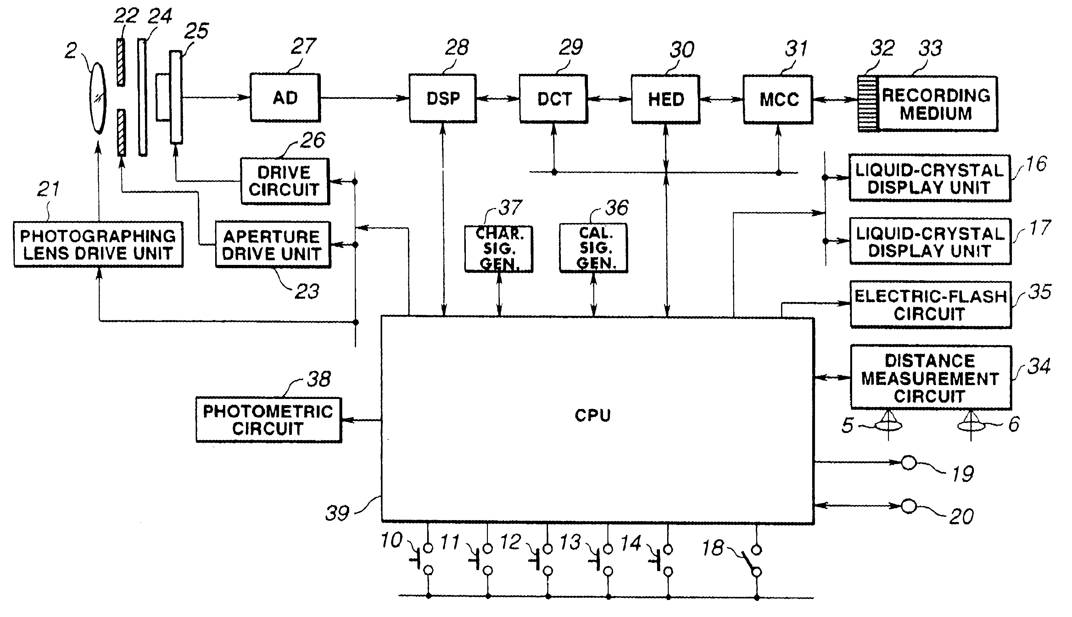
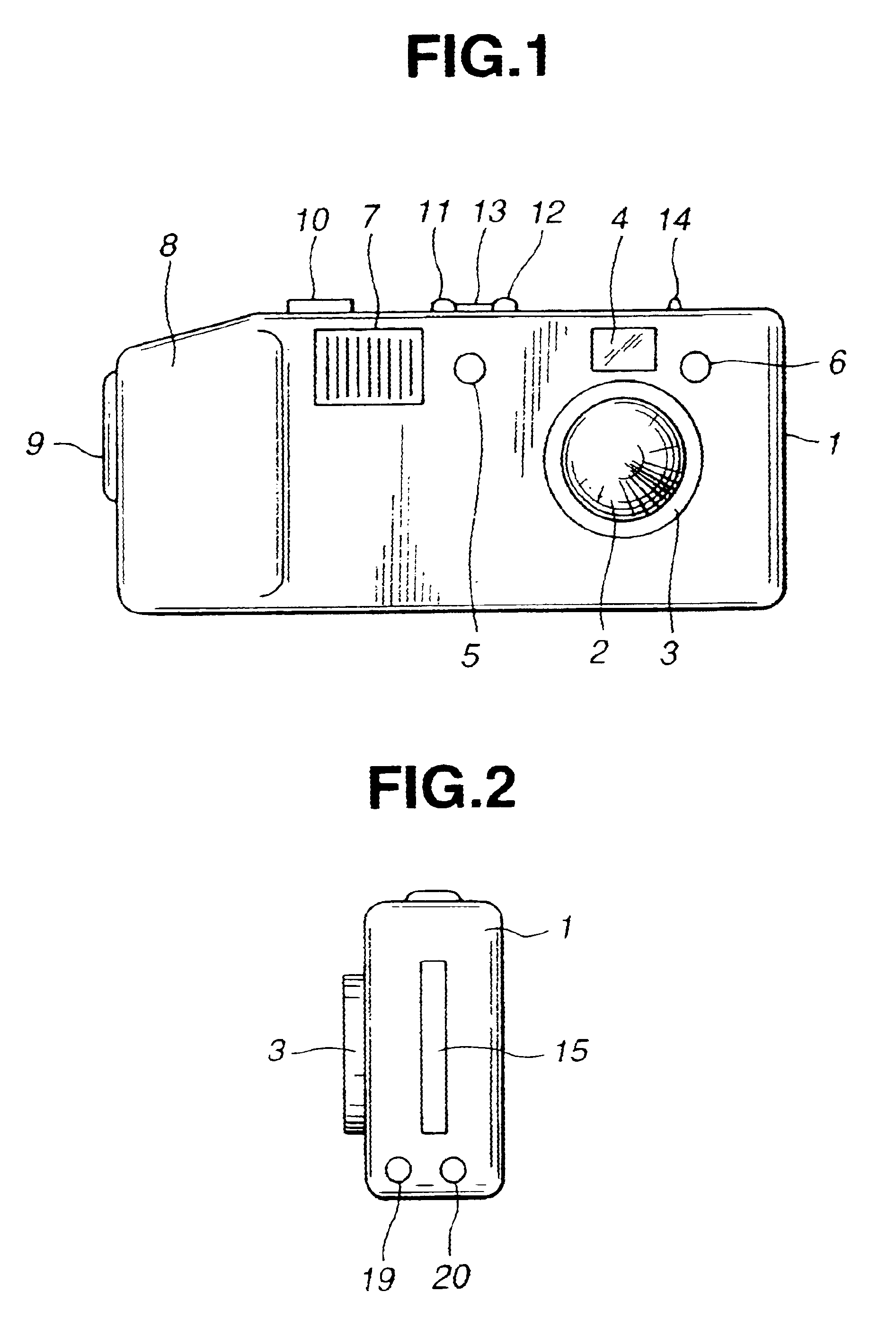
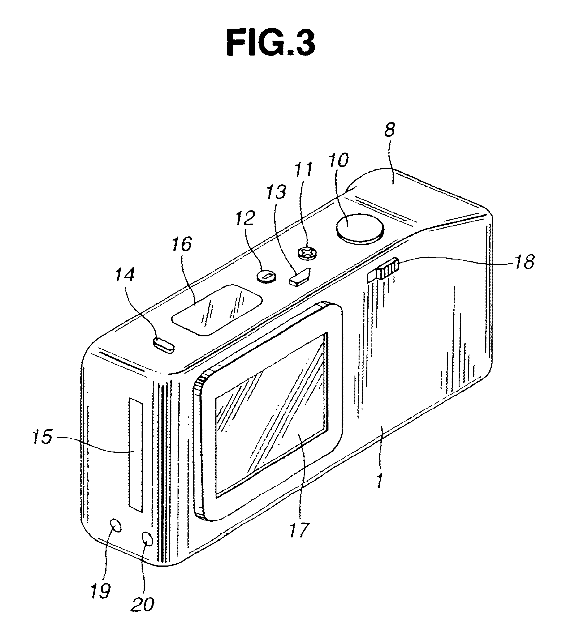
When the mode selection switch 14 arranged on the upper surface of the camera 1 is pressed, the mode is sequentially switched to various photographing modes or various process modes. This embodiment relates to a mode for performing panorama photographing (to be referred to as a "panorama mode" hereinafter) of these various modes.

This embodiment will be described below with reference to FIG. 6 showing a recording format of image information of each frame photographed and recorded on the recording medium 33, FIGS. 7 to 14 which are flow charts showing the flows of operations of this embodiment, and FIGS. 15 to 23 which are display examples of the liquid-crystal display unit 17 corresponding to the operations of this embodiment.

FIG. 7 is a main routine showing the entire flow of the operation of this embodiment.

The mode selection switch 14 is pressed to select a panorama mode while checking the liquid-crystal display unit 16...

second embodiment

FIG. 24 is a block diagram showing the entire electric arrangement of the camera according to the The arrangement and operation of the camera will be described below.

The output terminal of an angular velocity sensor 40 is connected to the input terminal of an A / D converter 42. The output terminal of the A / D converter 42 is connected to a CPU 39.

The angular velocity sensor 40 detects an angular velocity obtained when the camera is rotated about an y-axis which is a left-right direction when the camera is viewed from an object. An analog signal representing the angular velocity detected by the angular velocity sensor 40 is converted into a digital signal at a predetermined interval of time by the A / D converter 42, and the converted digital signal is subjected to time quadrature by the CPU 39. The digital signal subjected to time quadrature corresponds to an amount of rotation of the camera body 1 about the y axis. The rotation direction is determined by checking the polarity of the a...


PUM


Abstract

According to this invention, an electronic photographing device in which image information corresponding to one set of images photographed by panoramic photographing can be recorded on a recording medium includes: a rotation direction setting device for setting information corresponding to a rotating direction panoramic of the electronic photographing device in the panorama photographing; a rotating direction recording device for recording information corresponding to the rotation direction set by the rotation direction setting device on the recording medium; a control device for controlling an arrangement of the set of panoramic images on the basis of the information corresponding to the rotation direction recorded on the recording medium; a display device for displaying editing information for performing predetermined image editing to the panoramic images arranged by the control device; and a control device for performing a predetermined editing operation on the basis of the editing information displayed on the display device.

Description

1. Field of the InventionThe present invention relates to an electronic photographing device capable of panorama photographing.2. Related Art StatementConventionally, a photographing device capable of panorama photographing has been proposed. However, when the image data corresponding to a predetermined frame of a panoramic image photographed by the panorama photographing is erased, or when a protect code for inhibiting a write / read operation is recorded on the image data, an external, specially designed large-scale editing device is required.When the image data corresponding to the panoramic image photographed in the panoramic mode is stored in an external memory device, the following cumbersome operation is required. That is, a recording medium for recording the image data must be temporarily unloaded from the camera and loaded on the external memory device to store the image data in the external memory device.Additionally, a printer cannot be directly operated by a camera used in...

Claims


Application Information

Patent Timeline
IPC IPC(8): H04N1/21H04N5/77H04N5/232H04N1/387H04N9/804H04N9/82H04N1/00H04N5/907H04N5/765G03B17/18G03B17/24H04N5/225G03B19/02
CPCH04N1/215H04N1/3876H04N5/23238H04N5/23293H04N5/772H04N1/00323H04N1/00127H04N2201/3277H04N1/32101H04N5/765H04N5/907H04N9/8047H04N9/8205H04N2101/00H04N2201/0084H04N2201/3254H04N23/698
Inventor TOYOFUKU, TOSHIYUKIYAMASAKI, MASAFUMIDOTSUBO, NOBUHIDEHARUKI, TOSHINOBUHAYASHI, HIDETO
Owner XACTI CORP
Why Eureka
Try Eureka