
Apparel belt fastening tabs

a technology of belt fastening and tabs, which is applied in the direction of garment fasteners, garment belts, garment suspenders, etc., can solve the problems of cumbersome use of conventional belts, difficulty in dexterity required to use the prior art described above, and difficulty in hand and wrist mobility

Inactive Publication Date: 2004-01-20
Q LIFE
View PDF10 Cites 49 Cited by
  • Summary
  • Abstract
  • Description
  • Claims
  • Application Information

AI Technical Summary

Benefits of technology

Enables individuals with limited dexterity to unfasten their belts with less effort, promoting independence and reducing accidents, while maintaining a discreet and aesthetically appealing design.

Problems solved by technology

The level of dexterity required to use the prior art described above presents difficulties for some people.
In particular, very small children, the elderly, and those with conditions limiting hand and wrist mobility, can find using conventional belts cumbersome.
(a) Individuals with factors limiting their dexterity including the elderly, arthritis sufferers, stroke victims, wearers of prosthetic hooks and those with carpel tunnel syndrome, among many others, can unfasten our belt with less effort, than traditional buckle-fastened belts.
(b) Parents of toddlers can use the present invention as a pottie training aid as it allows their little one to open their belt all by themselves. The independence gained can help build confidence and self-esteem.
(c) Wetting accidents, and the associated embarrassment, can be reduced due to the quick release design. Most belts made for children were not designed for children. They are simply adult-styled belts made smaller.
(d) Many daycare providers follow a Hands-Off policy regarding children and restroom use, advising parents to ensure their child can remove and replace their own clothing. The present invention can make it easier for all to comply with applicable rules.
(e) The aforementioned individuals can appreciate and enjoy the discreet appearance and aesthetic value of a piece of adaptive equipment that looks just like a regular belt.

Method used


Image

  • Apparel belt fastening tabs
  • Apparel belt fastening tabs
  • Apparel belt fastening tabs

Examples


Embodiment Construction

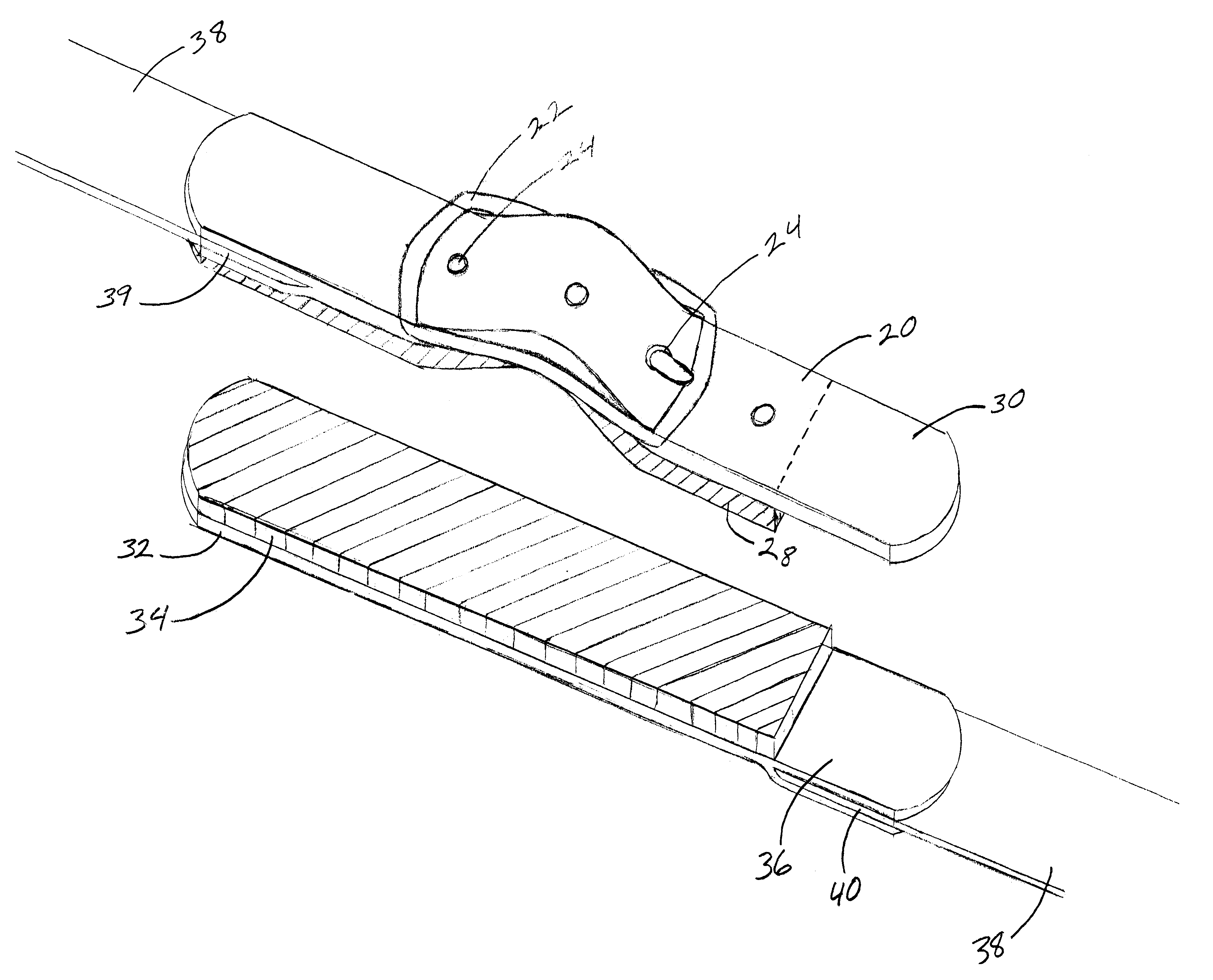
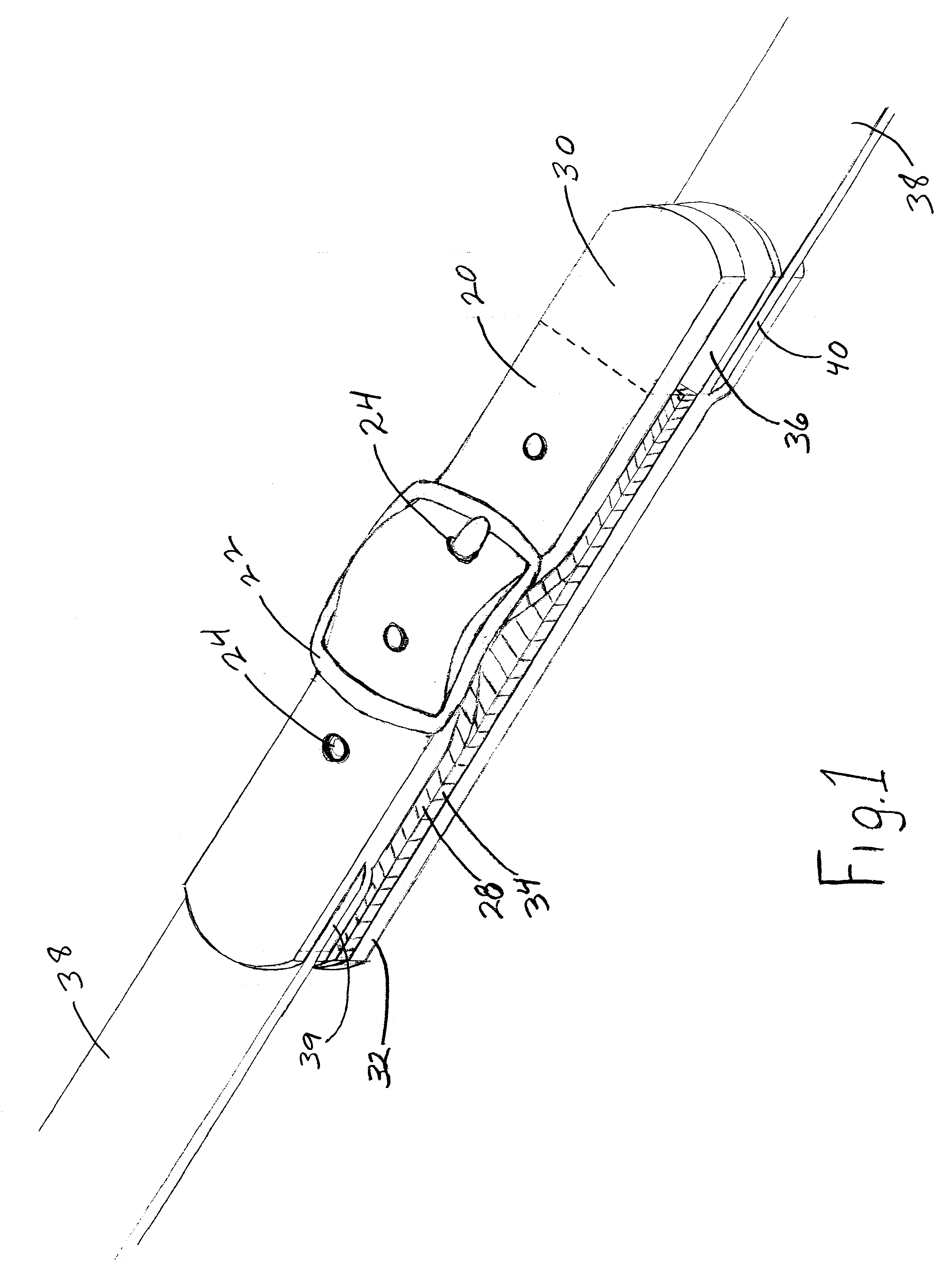
FIG. 1 shows a perspective view of a basic version of our belt fastener. The two main components of the belt fastener are an elongated front end-tab 20 and an elongated rear end-tab 32. One end of a torso-encircling strap 38 is permanently attached to the left end of front end-tab 20 and the other end of the same strap 38 is permanently attached to the right end of rear end-tab 32. FIG. 1 shows front end-tab 20 and rear end-tab 32 releasably attached to each other in an overlapping fashion. FIG. 1 also shows buckle 22 in place.

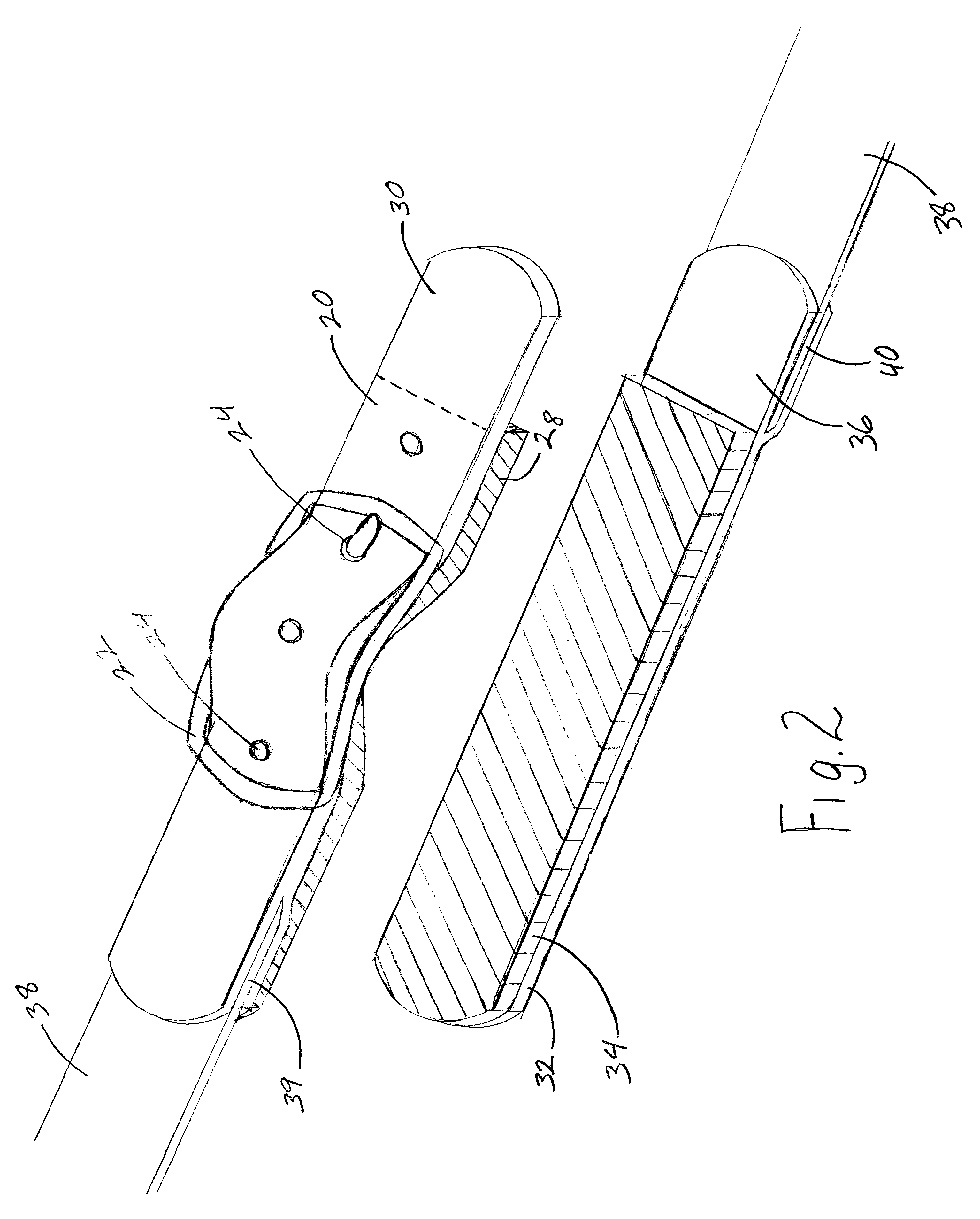
FIG. 2 shows a perspective view of our belt fastener in which front end-tab 20 and rear end-tab 32 have been separated by disengaging Velcro hooks 28 from Velcro loops 34. FIG. 2 also shows buckle 22 in place. Note that Velcro hooks 28 do not cover front end-tab 30 completely. This uncovered area forms front tab pull-grip 30. Note that Velcro loops 34 do not cover rear end-tab 32 completely. This uncovered area forms rear tab pull grip mate 36.

FIG. 3 shows an ...


PUM


Abstract

Two elongated, flat, belt end-tabs (20) and (32) made of a material suitable for permanent attachment to opposite ends of a torso-encircling strap (38). The first said belt end-tab (20) having Velcro hook (28) material attached lengthwise to it's underside and, the second said belt end-tab (32) having Velcro loop (34) material attached lengthwise to it's topside. Said belt end tabs (20) and (32) being releasably attachable to each other in an overlapping fashion by the mating of said Velcro hook (28) and said Velcro loop (34). Said Velcro hook (28) being a predetermined length so that approximately one inch of the free end of said belt end tab (20) is left uncovered so that pull-grip (30) is formed. In addition, a belt buckle (22) is mounted to the first said belt end tab (20) by means of a buckle positioning hole (24) which gives the assembly the deceptive appearance of being fastened with a buckle.

Description

1. Field of InventionThis invention relates to the clothing accessory commonly known as an apparel belt, and specifically, to those devices used to connect the opposite ends of a belt around the wearer's waist.2. Description of Prior ArtBelts of various types are commonplace and have been used to hold up trousers for as long as pants have been worn. Generally, the opposite ends of a belt are fastened together to encircle the wearer's torso. The fastening is accomplished in a number of different ways; from the simple knot-in-a-rope to all sorts of buckles and clasps.A common construction for apparel belts is where a leather end-tab is sewn to each end of a strap of webbing. A first end-tab has a buckle attached to it, and, a second end-tab has an aligned plurality of holes. The two end-tabs are fastened together by inserting the second end-tab through the buckle's opening, then, inserting the buckle's tongue through one of the holes. This action is known as "buckling" the belt and, c...

Claims


Application Information

Patent Timeline
Patent Type & Authority Patents(United States)
IPC IPC(8): A41F1/00A41F9/00
CPCA41F1/002A41F9/00
Inventor JONES, RODNEY L.JONES, ANGELA
Owner Q LIFE
Learn More