Vehicle suspension with camber control

a camber control and suspension technology, applied in the direction of resilient suspensions, vehicle springs, vehicle components, etc., can solve the problems of affecting the effect of the suspension, affecting the stability of the vehicle, and unable to implement the suspension on most current vehicles

Inactive Publication Date: 2004-02-10
MICHELIN RECH & TECH SA
View PDF45 Cites 30 Cited by
  • Summary
  • Abstract
  • Description
  • Claims
  • Application Information

AI Technical Summary

Benefits of technology

According to another embodiment, the degree of camber freedom is provided by resilient deformations of deformable elements which connect the wheel carrier to the suspension elements.
Such suspension device is designed to connect a wheel carrier to a body of a vehicle, which wheel carrier is designed to support a wheel, of a radius "R", designed to be supported on the ground through a contact area, and comprises means which provide the wheel carrier, relative to the body, with a degree of freedom of camber and a degree of freedom of suspension movement which are independent from one another. The suspension devise is configured such that the camber movement of the wheel carrier, about a mean position, relative to the body, allows a second instantaneous center of rotation, which is situated in an interval ranging from 0.5 R above the ground to R beneath the ground. The suspension device according to the invention comprises two degrees of freedom, which permit independent movements of suspension and camber. The camber movement of the wheel (or of the wheel carrier) takes place about a second instantaneous center of rotation, which is situated at a limited distance from the contact area, in order to limit the track variations during the process of camber or counter-camber and to limit the energy necessary in the case of active control of the camber.

Problems solved by technology

These devices require a specific design and vehicle architecture, which cannot be implemented on most current vehicles for reasons of space requirement and cost.
These systems react only to the consequence (deflection, rolling) of a transverse acceleration and not to the forces which cause it, thereby, on the one hand, delaying the effect of the correction.
Moreover, to permit a sufficient variation of the camber, the kinematics of these systems require displacements of the position of the contact area with respect to the vehicle, called "track changes", and these variations can also create difficulty.
The range of camber corrections made possible by such systems is therefore relatively limited when the compromise necessary for the correct functioning of the other load cases, such as travelling on a bumpy road, unilateral or in contrast simultaneous bouncing, is to be observed.
These systems are very specific, since they cannot be used in the most ordinary vehicles, in particular because of their space requirement and the considerable power necessary for the actuators.
This equilibrium can be unstable equilibrium.

Method used


Image

  • Vehicle suspension with camber control
  • Vehicle suspension with camber control
  • Vehicle suspension with camber control

Examples


Embodiment Construction

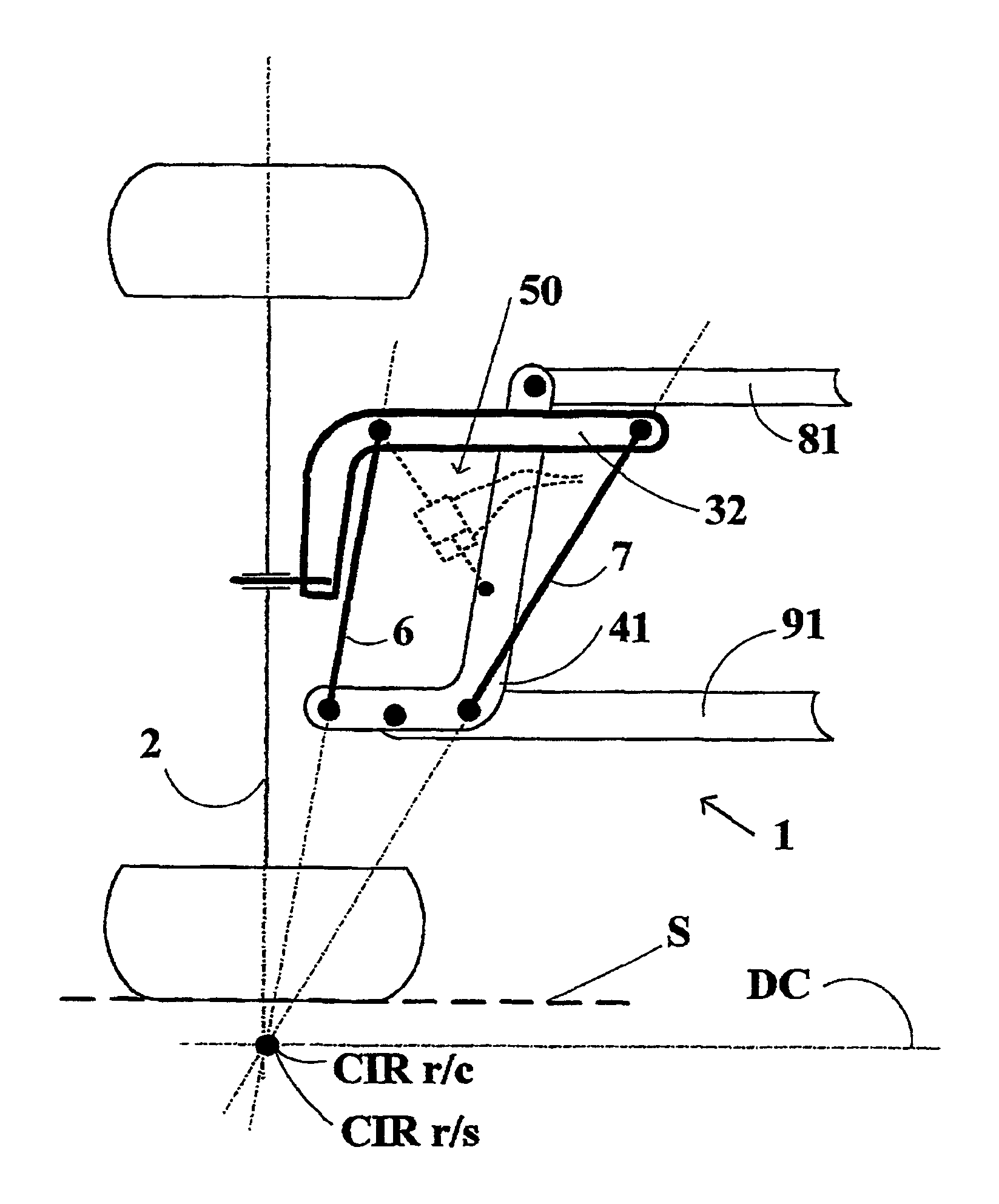
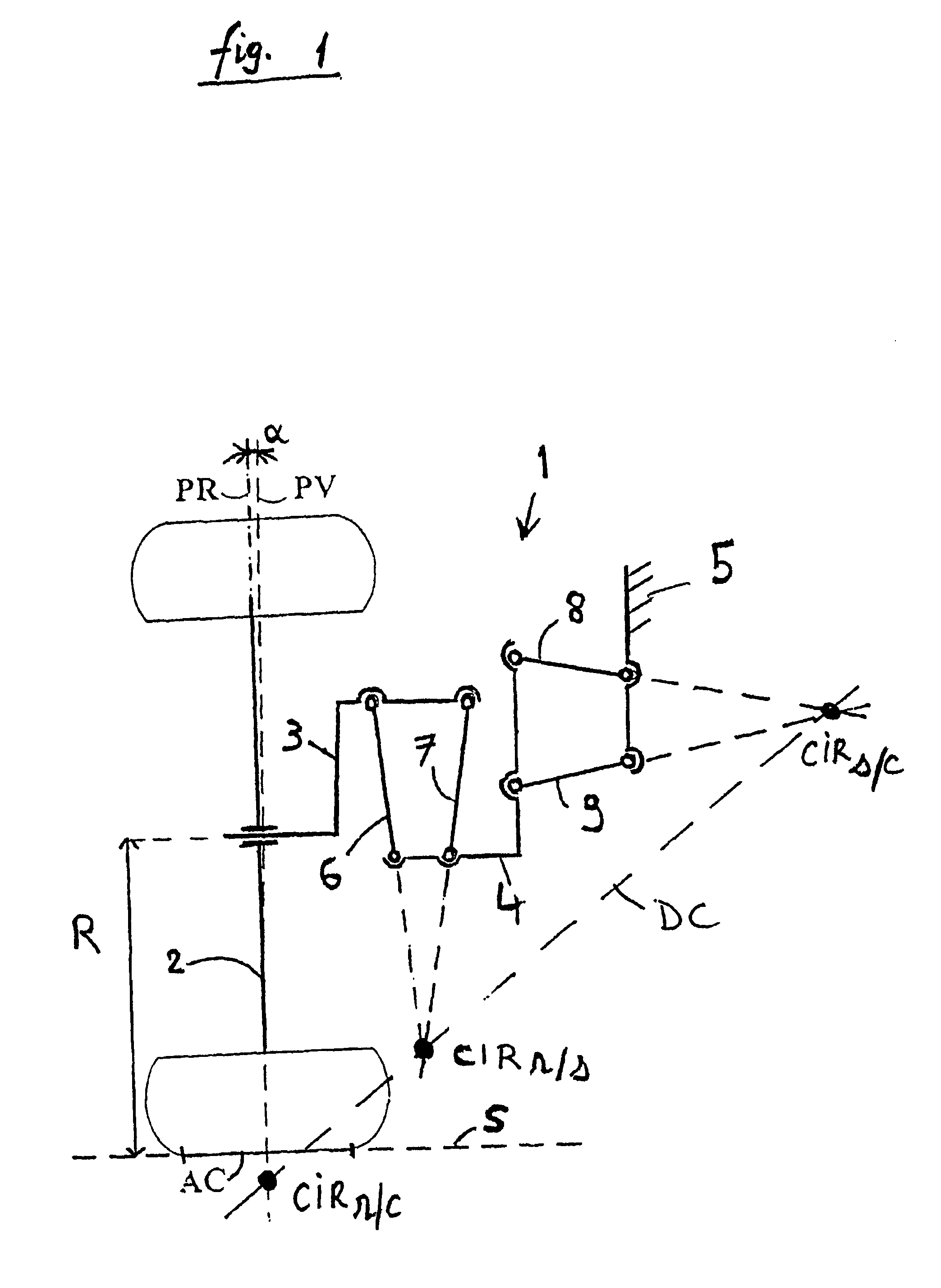
FIG. 1 represents in a flat longitudinal view the principle of a suspension device according to the invention. This flat representation (i.e. in two dimensions) is very convenient, since it shows clearly how the device according to the invention is distinguished from the devices according to the state of the art.

The suspension device 1 comprises a wheel carrier 3, which is designed to maintain the plane PR of a wheel 2 relative to the body 5 of a vehicle. The wheel, which has a radius "R", is supported on the ground S through its contact area AC. The wheel carrier 3 is connected to the body 5 by means (4, 6, 7, 8, 9) which allow it two degrees of freedom. The camber movement of the wheel is permitted by a connection of the wheel carrier 3 to an intermediate support 4 by connection rods 6 and 7. The suspension spring movement is permitted by a connection of the intermediate support 4 to the body 5, by upper 8 and lower 9 arms (or triangles). Thus, the suspension device is configured ...


PUM


Abstract

A vehicular suspension device comprises a wheel carrier which is articulated relative to the suspension elements. This connection is provided by rigid connection rods. This additional degree of freedom permits variation of the camber angle independently of the suspension spring movement and of the deformations of its elements. The variation of the camber is preferably controlled by the forces sustained by the wheel in the ground contact area of the tire. This is obtained by a configuration in which the movements of the wheel relative to the body of the vehicle allow an instantaneous center of rotation which is situated beneath the plane of the ground.

Description

1. Field of the InventionThe present invention relates to chassis systems for vehicles, in particular suspension devices, and more particularly the guidance of the wheels. Suspension devices have two main functions which must be fulfilled simultaneously at any moment during operation. One of these functions is that of suspending the vehicle, that is to say, permitting substantially vertical oscillations of each wheel in accordance with the load applied to the wheel. The other function of these devices is that of guiding the wheel, that is to say, controlling the angular position of the wheel plane.2. The Related ArtThe term "wheel plane" refers to the plane, associated with the wheel, which is perpendicular to the axis of the wheel and which passes through the center of the contact area with the ground. The angular position of the wheel plane with respect to the body of the vehicle is defined by two angles, the camber angle and the steering angle. The camber angle of a wheel is the ...

Claims


Application Information

Patent Timeline
Patent Type & Authority Patents(United States)
IPC IPC(8): B60G15/07B60G13/00B60G15/00B60G3/26B60G7/00B60G3/18B62D17/00B60G17/015
CPCB60G3/265B60G7/006B60G7/008B60G13/005B60G15/07B62D17/00B60G2200/142B60G2200/17B60G2200/46B60G2202/312B60G2204/129B60G2204/422
Inventor SERRA, LOICTETAZ, CHRISTIAN
Owner MICHELIN RECH & TECH SA
Why Eureka
Try Eureka