Headphone earmuffs

a headphone and earpiece technology, applied in the field of ear muffs, can solve the problems of difficult use of both in unison, large size, weight, and more expensive to be practically adapted for outdoor use, and speakers that do not lend themselves to protecting the ear, so as to reduce the random repositioning of speakers during us

Inactive Publication Date: 2004-03-02
DAW JEFFREY LEWIS
View PDF17 Cites 9 Cited by
  • Summary
  • Abstract
  • Description
  • Claims
  • Application Information

AI Technical Summary

Problems solved by technology

Due to their size and construction the speakers do not lend themselves to protecting the ear against cold weather.
Larger headphones do exist that completely cover the ear, but do not have the design elements necessary for proper insulation in cold weather and they are considerably larger, heavier and more expensive to be practically adapted for outdoor use.
Using both in unison becomes difficult due to the multiplicity of bands and earpieces.
Prior art does not allow for the use of the headphone earmuff with the wide variety of headphones already available on the market.
Additionally, the design in U.S. Pat. No. 4,546,215 limits the size of the earmuff because it is constructed with a spring loop that defines the circumference of the earmuff.
In conclusion, the design above in U.S. Pat. No. 4,546,215 limits its uses with the various styles of headphones on the market having only the capability to work in conjunction with a few that meet its limited physical dimension criteria.
It is apparent by this designs functionality that it requires complex manipulation of the matching pieces to properly align and therefore use this item.
In addition, once the flaps are properly in place, small adjustments necessary to keep the earmuff in proper alignment with the headphone speakers proves difficult due to the fact that the two flaps completely encase the headphone speaker and there for allow for little movement with out the need to completely separate and reattach the flaps together in new alignment.
Proper positioning of the earphone inside the sandwich pocket is possible, but due to the lack of structure and support proves difficult to maintain.
This lack of insulation and respective area coverage around the ear proves inadequate as a proper insulating device in extreme cold weather.
It is by the creation of this pocket, either by the matching of cloth flaps in U.S. Pat. No. 4,654,898 or a cloth pocket framed by a spring loop, in U.S. Pat. No. 4,546,215, that both designs fail to provide adequate insulation necessary to protect the ear and surround area of the head.
By having a pocket as the center of the earmuff to accommodate the speaker the space is no longer available for insulation.
And due to size restrictions inherent in each design, there is little space and or surface area available to adequately be used for insulating the ear.
In extreme cold conditions the designs will not match the insulating efficiency of a fully padded earmuff.
The earmuff can not be used with other headsets on the market due to this design.
Therefore, this type of prior art does not provide an earmuff designed to be used with the variety of headphones on the market as my invention does.
In conclusion, prior art earmuffs built to accommodate headphone speakers have not solved the problem of incorporating the headphone speaker inside the earmuff without sacrificing insulation and or allowing the muff to be any size or shape.
In addition, the designs of prior art have failed to make an ear muff capable of being used with the many styles and shapes of portable headphones on the market.
In addition, prior art incorporates designs that either inconvenience the user with their complexity having such things as flaps to align and maintain as in U.S. Pat. No. 4,654,898 or spring loops to snap over one style of headphone as in U.S. Pat. No. 4,546,215.
These designs are inconvenient to users that choose different headphone styles.
Further, the prior art discussed cannot be made into shapes such as triangles or squares or enlarged circles due to their design limitations.
The prior art discussed above is limited both in design as well as use of materials for accomplishing the same usefulness as the standard earmuff described here.

Method used


Image

  • Headphone earmuffs
  • Headphone earmuffs
  • Headphone earmuffs

Examples


Embodiment Construction

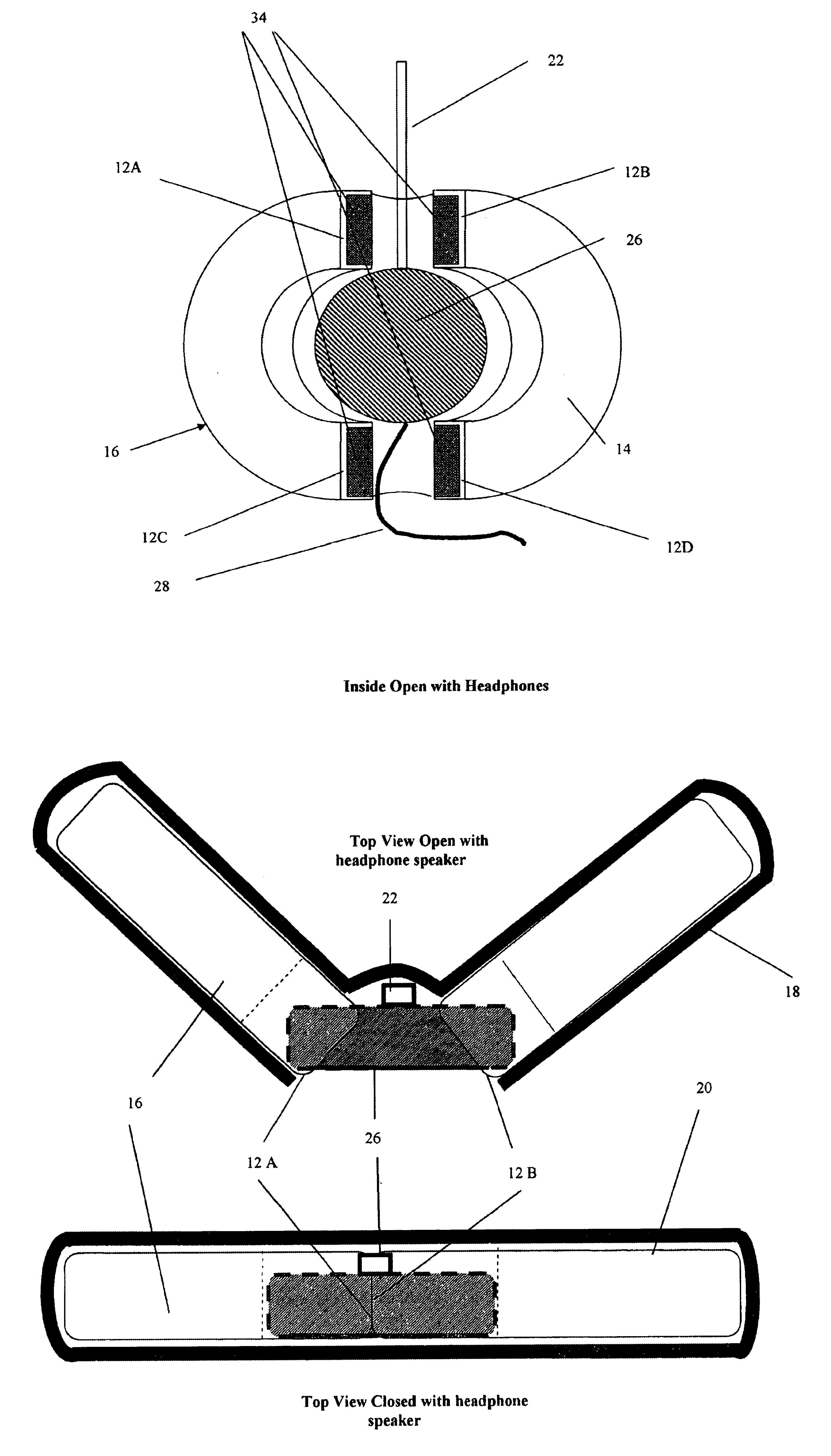
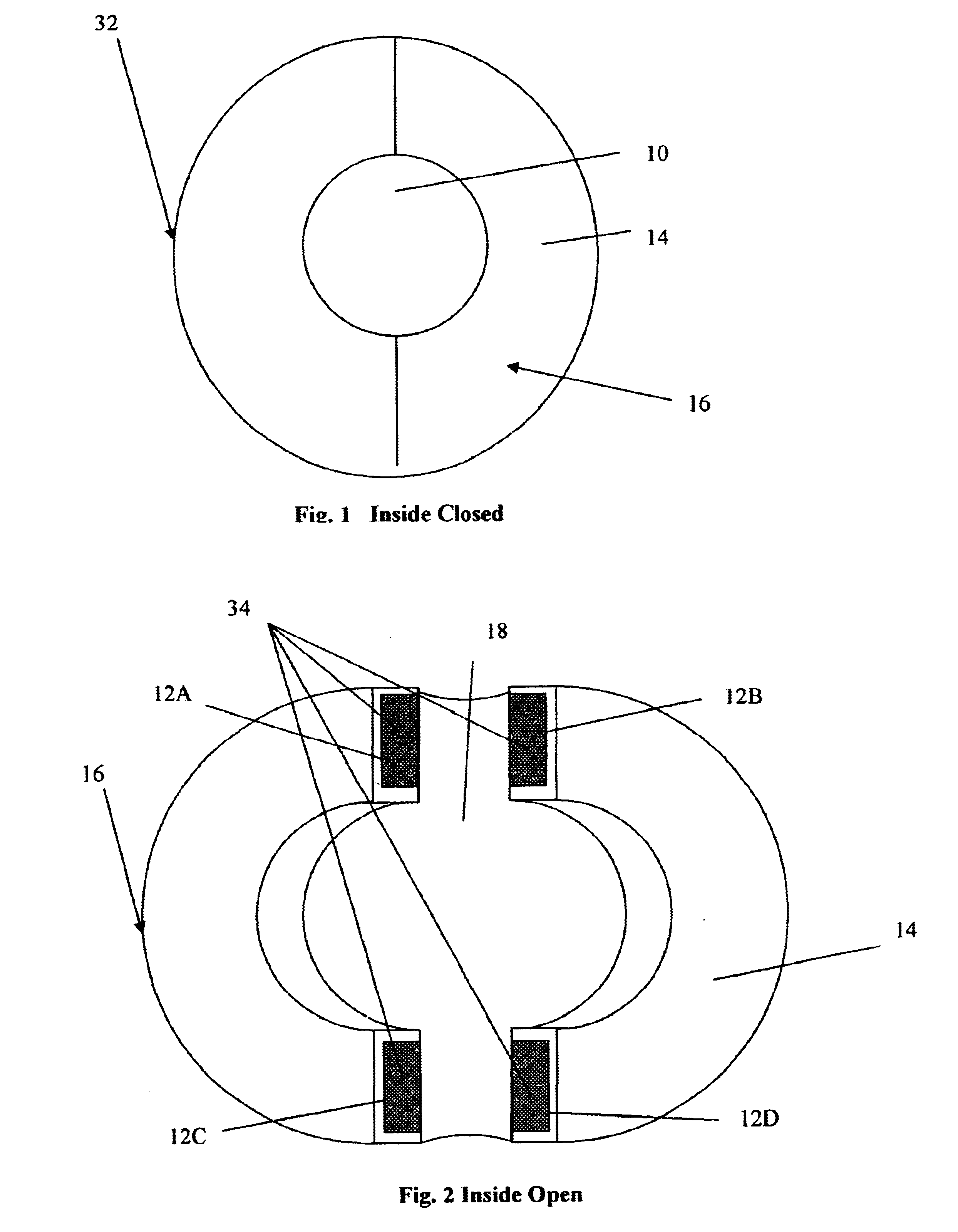
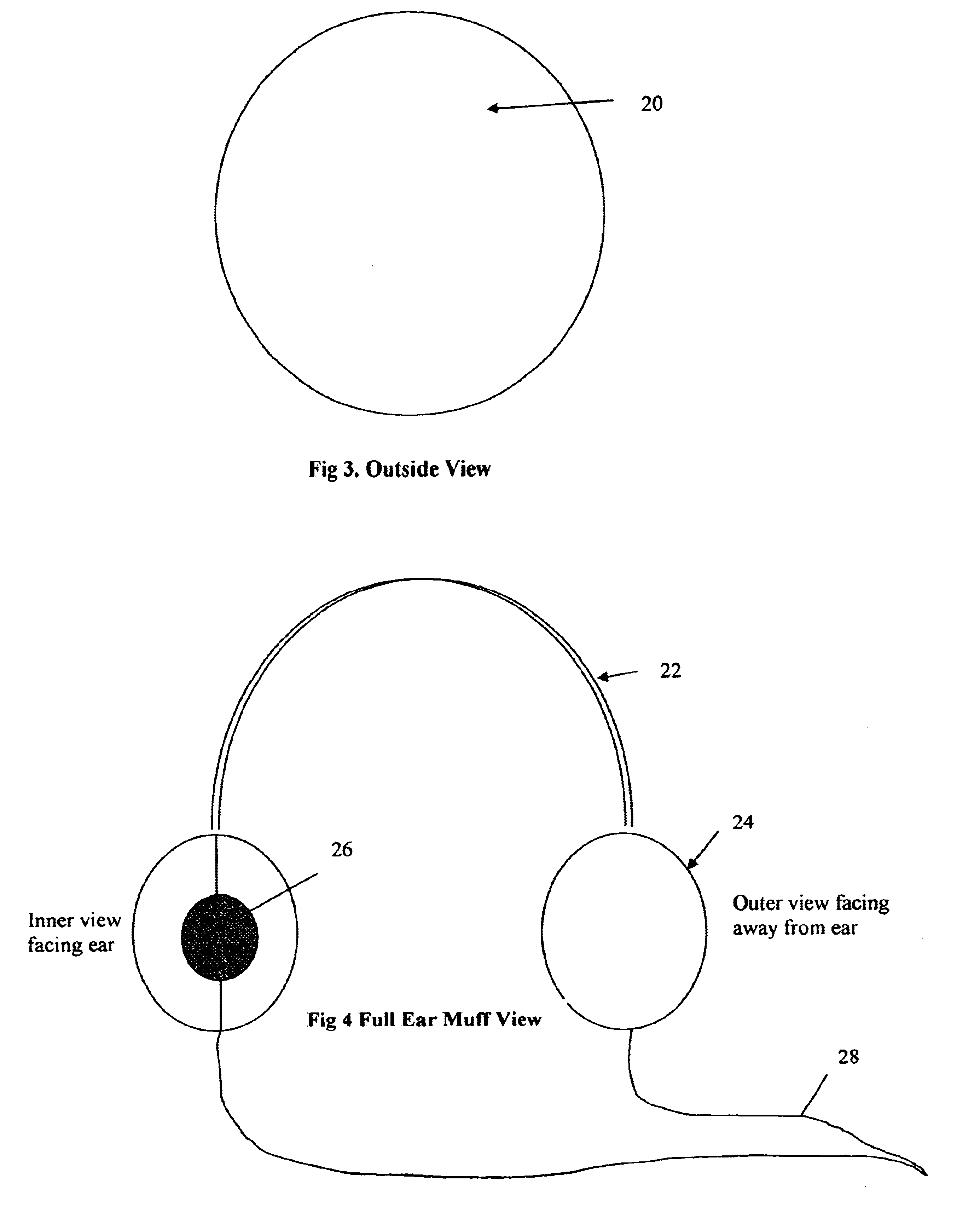
FIG. 1 shows a perspective view of the headphone earmuff. The inner structure is constructed out of foam material or the like of a thickness that is rigid enough to hold the shape of a round disk cut in half and bored out in the center so that the structure is that of a donut cut in half. The two halves of the foam donut are then fastened together with hook and loop type fastener. A speaker space 10 in the middle is created when the two-donut halves 16 are fastened together. This speaker space 10 is occupied with a headphone speaker 26 where a band 22 follows between planar sides 12a and 12b at the top of the connecting donut. Planar sides 12c and 12d at the bottom of the split donut reconnect around the headphone speaker 26 and speaker wire 28 allowing it to exit the earmuff.

An outer covering of the foam donut, comprised of the connecting C shape halves 16, is covered with fabric on its outer surface 20 said fabric enclosing each donut half 16, whether in open position or closed. B...


PUM


Abstract

The present invention relates in general to ear muffs and in particular to an earmuff that are to be used in conjunction with headphones for portable radios, cassette players and the like. The outer surface of the earmuff is a solid shape resembling a standard earmuff while the inner side that faces the ear breaks apart into 2 C-shape donut halves to accommodate the placement of the headphone speaker. This design allows the earmuff to be positioned around the headphone speaker by means of the 2 C-shape donut halves and reconnect together around the headphone speaker in order to stabilize against the headphone and allow space for the headphone band and speaker wire between the connected respective halves of the donut. The earmuff makes use of the unique donut design to accommodate various styles of portable headphones while providing maximum insulation to the ear. The earmuffs are detachable and can be exchanged. The earmuff in this invention can be made of various materials customary to cold weather clothing accessories, such as wool, cotton and the like. The earmuff is designed to encompass and protect the headphone speaker from weather elements as well as being made of materials high in insulating capacity and being of a size to envelop the ear of the wearer as well as the surrounding part of the head as is similar to the coverage and insulation provided by typical earmuffs on the market.

Description

Not applicable1. Field of InventionThis invention relates in general to ear muffs, specifically to ear muffs that are to be used in conjunction with headphones for portable radios, cassette players and other media players of the like.2. Description of Prior ArtThe Earmuff originally was designed to protect the ears from cold weather. The Earmuffs consisted of two insulated cushions or muffs usually round or oval typically attached together with a flexible curved center section or band. The band extends over the head of the wearer and has at each end, the padded earmuff piece that is permanently affixed to be in register with the ear of the wearer.For purposes of definition, the standard earmuff commonly available on the market today, will be defined to include the above description as well as the following features. The typical earmuff consists of two pads or muffs commonly filled with insulating padding and covered with an insulating material such as cloth, fur--synthetic or otherw...

Claims


Application Information

Patent Timeline
Patent Type & Authority Patents(United States)
IPC IPC(8): H04R1/10
CPCH04R1/1008H04R1/1058
Inventor DAW, JEFFREY LEWIS
Owner DAW JEFFREY LEWIS
Why Eureka
Try Eureka