
Heart valve with rectangular orifice

a heart valve and rectangular technology, applied in the field of mechanical heart valve prostheses, can solve the problems of obstructing the central flow of blood, bileaflet valve design still partially obstructing the blood flow, and risk of thrombosis of the valve that can foul the mechanism,

Inactive Publication Date: 2004-03-02
MAZZUCCO DANIEL CLARKE +2
View PDF20 Cites 1 Cited by
  • Summary
  • Abstract
  • Description
  • Claims
  • Application Information

AI Technical Summary

Problems solved by technology

The tilting disk heart valves have improved flow characteristics over the caged ball valves, but still partially obstruct the central flow of blood while open.
However, bileaflet valve designs still partially obstruct the blood flow when the leaflets are open.
A major drawback of existing mechanical heart valves is the risk of thrombus formation on the valve that can foul the mechanism.
Additionally, such thrombi can embolize and lead to medical conditions such as stroke, heart attack, and pulmonary embolism.
Presently, mechanical heart valve recipients receive anticoagulant drug therapy in order to avoid thrombus formation; however, this drug therapy introduces a new set of comparable health risks.
If the occluder mechanism of a valve lies in the central region of flow when the valve is open, its surfaces induce drag on the high velocity fluid causing additional shear forces and turbulence in the fluid.
Some valve designs move the occluders out of the direct center of flow when the valve is open by employing three or more leaflets; however, there is still significant flow occlusion.
Additionally, these designs increase the number of moving parts, which, in turn, increases the probability of mechanical failure.
The major drawback of mechanical valves, vis a vis bioprosthetic valves, is that patients require anti-coagulation therapy.
Flow without obstructions is more efficient than flow with obstructions, and flow through a smaller orifice is less efficient than flow through a larger orifice.
Each physical manifestation of these shapes has complex irregularities that affect flow efficiency, but the inherent geometric disadvantages are dominant factors.
The second result of central flow obstruction is shear damage.
Thus shear has increased significantly, and blood is increasingly damaged.
In the final comparison of this design with the prior art in light of the above design principles, other aspects of geometry can contribute to blood trauma.
However, increasing the number of leaflets increases the number of parts, which increases the risk of mechanical failure.
In addition, more leaflets increase the risk of performance failure, and leaflet closure complications can be catastrophic.
Any damage to a leaflet that might impair simultaneous closing leads to regurgitation, which stresses the heart.
Hence increasing the number of leaflets beyond two incurs additional risk that has not yet been shown to provide concomitant benefit for patients.

Method used


Image

  • Heart valve with rectangular orifice
  • Heart valve with rectangular orifice
  • Heart valve with rectangular orifice

Examples


Embodiment Construction

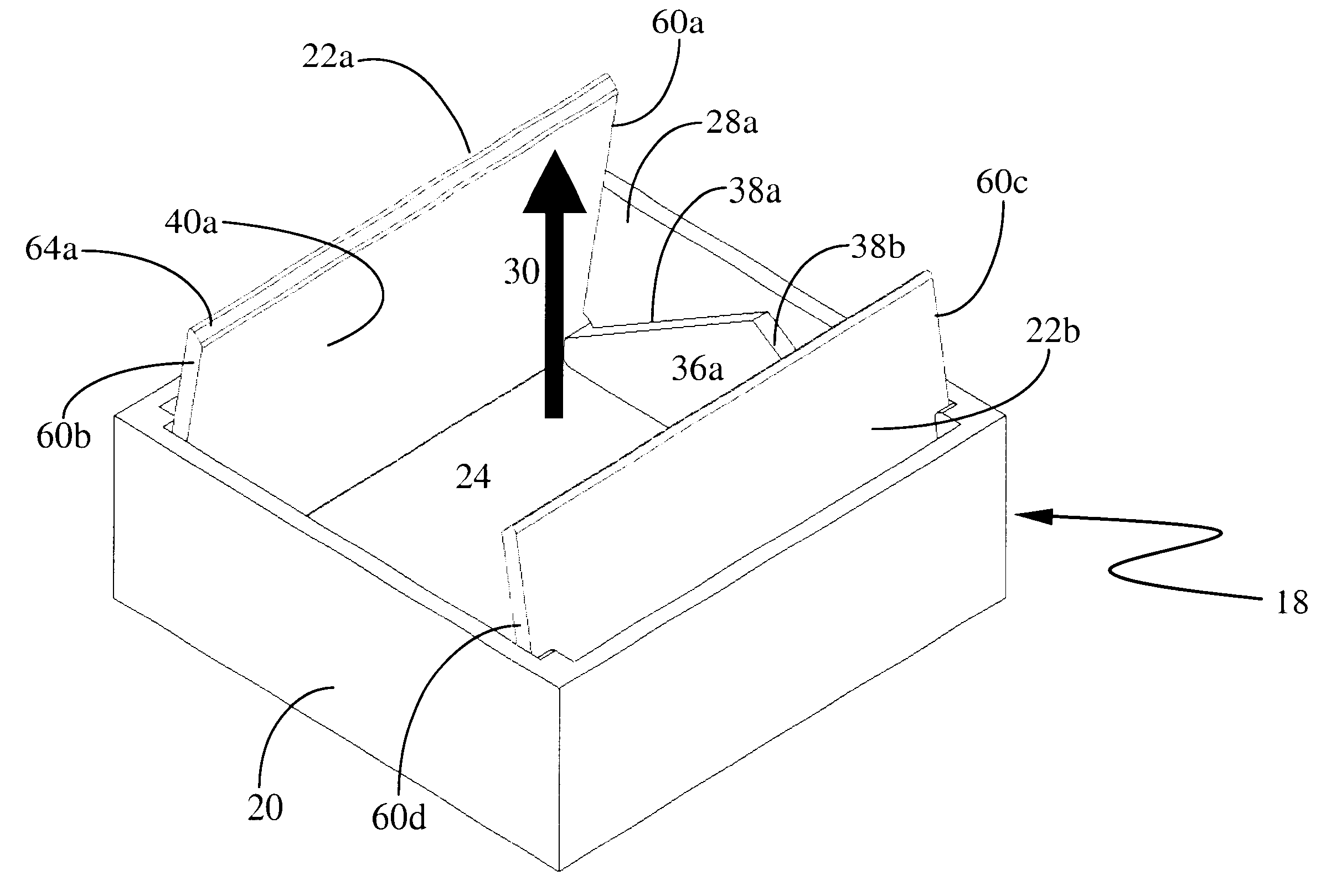
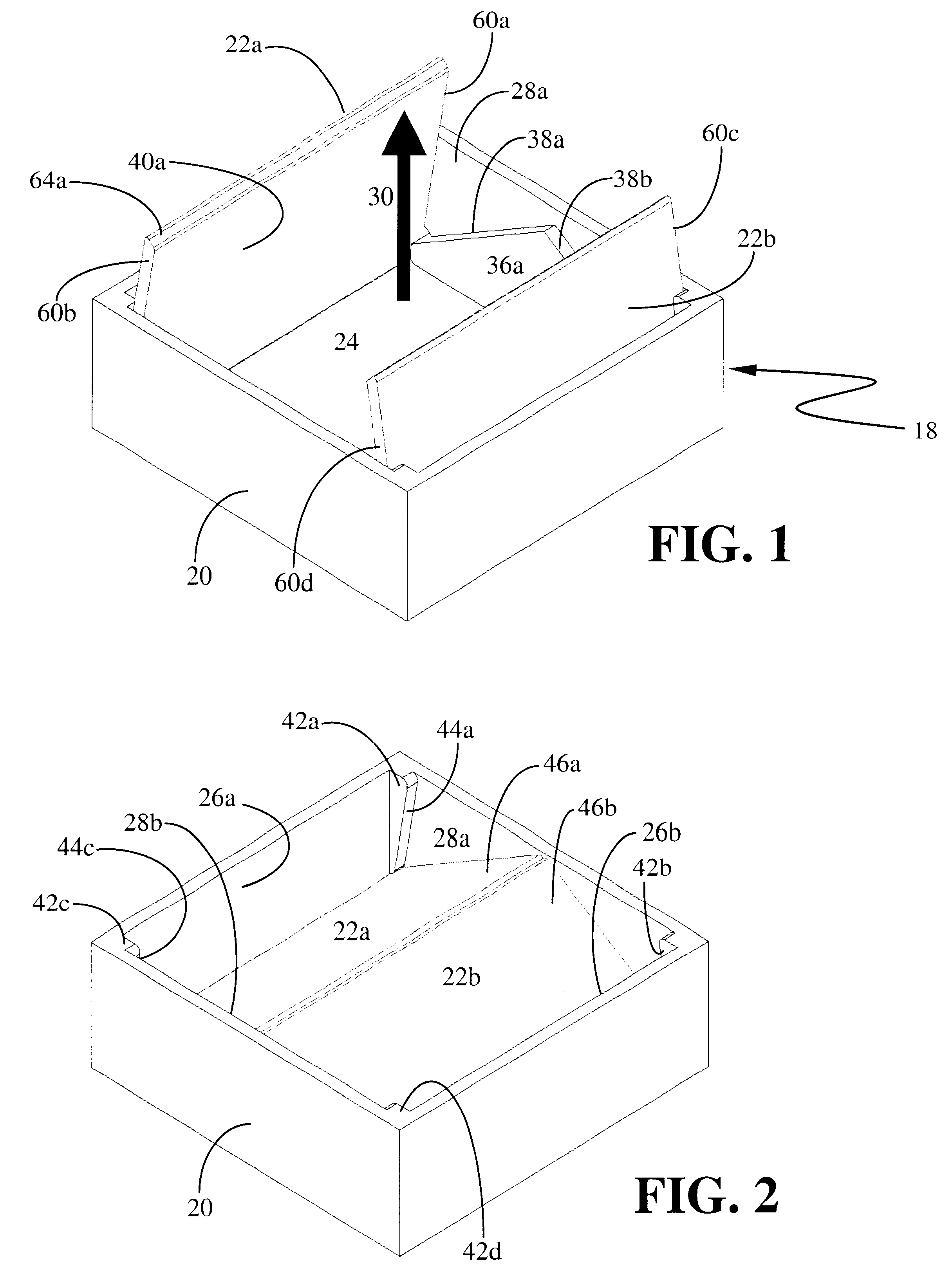
Referring now to FIG. 1 and FIG. 2, there is shown a preferred embodiment of the present valve which is a valve 18 formed of a base 20 and leaflets 22a and 22b. The base 20 is a generally rectangular member whose internal back walls 26a and 26b and internal side walls 28a and 28b define the orifice 24 and enclosed blood passageway. The arrow shows the general direction of blood flow 30.

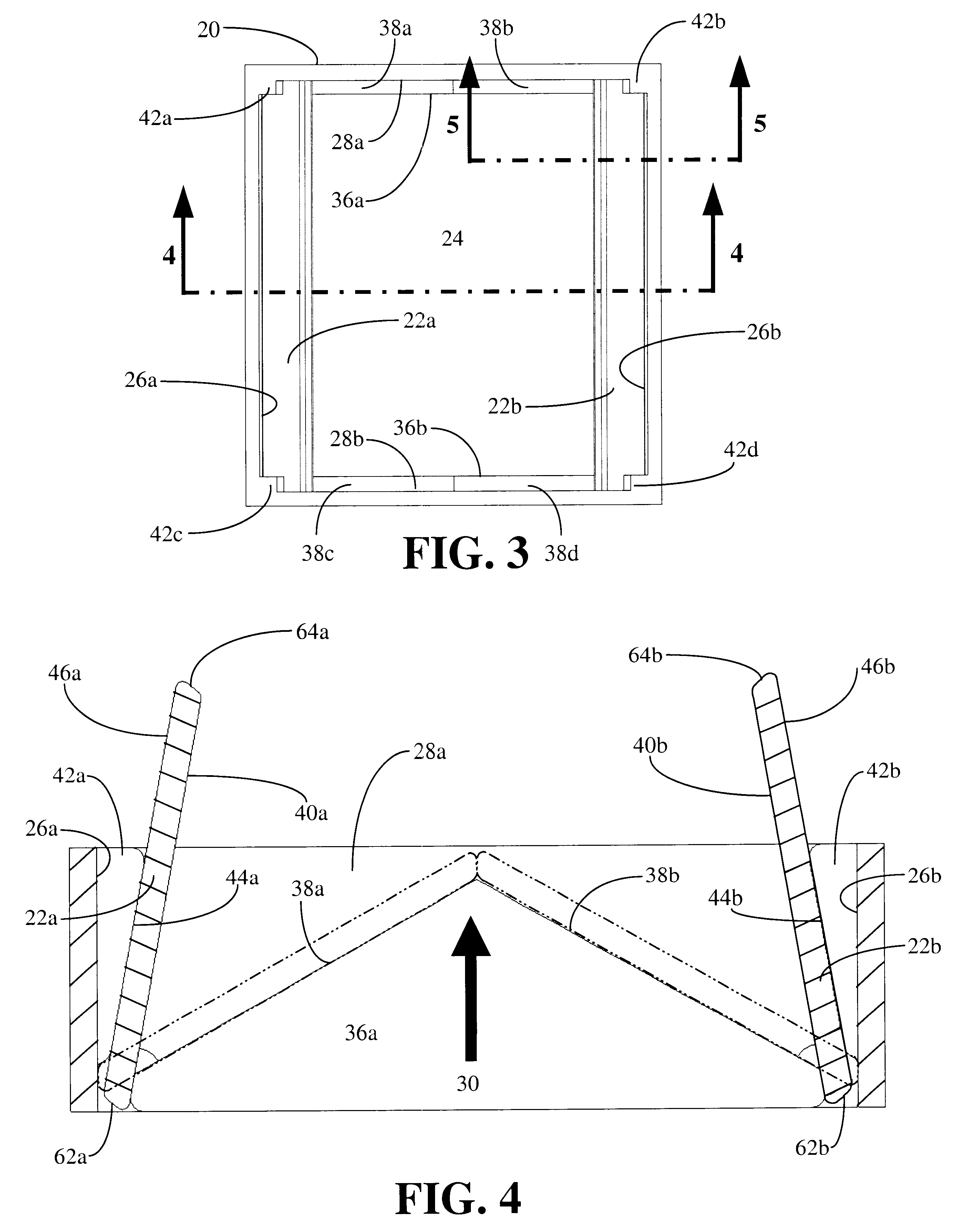
Referring now to FIG. 3, there is shown a direct view of valve 18 from downstream of the embodiment of FIG. 1. Shown are shelves 36a and 36b that project from internal side walls 28a and 28b forming closing stops 38a and 38b. Protrusions 42a, 42b, 42c, and 42d project from side walls 28a and 28b forming opening stops 44a, 44b, 44c, and 44d.

Referring now to FIG. 4, there is shown a cross-section taken along the line 4--4 in FIG. 3. Leaflets 22 are shown in open position, and are also indicated in closed positions by phantom lines. Shelf 36a forms closing stops 38a and 38b to mate with undersides 40a an...


PUM


Abstract

A mechanical heart valve prosthesis has a generally rectangular orifice and two leaflets that move between a closed position nearly perpendicular to blood flow and an open position nearly parallel to blood flow. Due to the uniform dimension of a rectangle, the leaflets are hinged at the periphery of the orifice, and present a single large central flow region to the blood when opened. The base provides several means of constraining the leaflet rotation during opening and closing.

Description

STATEMENT REGARDING FEDERALLY SPONSORED R & DNot applicable.REFERENCE TO SEQUENCE LISTINGNot applicable.1. Field of InventionThe present invention relates to mechanical heart valve prostheses, and, in particular, to a bileaflet prosthetic heart valve with a rectangular orifice and periphery that enable full leaflet opening for improved blood flow with a single central orifice.2. Description of Prior ArtA wide variety of heart valve prostheses have been developed to operate hemodynamically in conjunction with the pumping action of the heart to replace defective natural valves. These valves generally have annular valve bodies that function with a single occluder or a plurality of occluders that allow forward blood flow through the valve during systole and prevent retrograde flow during diastole.The first successful mechanical heart valves were caged ball valves, pioneered by Starr and Edwards, based on the ball valve of U.S. Pat. No. 19,323 (Williams, 1858). The hemodynamic concept of...

Claims


Application Information

Patent Timeline
Patent Type & Authority Patents(United States)
IPC IPC(8): A61F2/24
CPCA61F2/2403A61F2/2409
Inventor MAZZUCCO, DANIEL CLARKEHARTEMINK, CHRISTOPHER ALLANNEWBURG, SETH OWEN
Owner MAZZUCCO DANIEL CLARKE
Learn More