Heart Valve Inserter

a heart valve and inserter technology, applied in the field of inserters, can solve the problems of difficult to facilitate the passage of the leading end of the heart valve prosthesis through the annulus, and achieve the effect of smooth inserting and convenient passag

Active Publication Date: 2007-09-20
VALVE SPECIAL PURPOSE CO
View PDF9 Cites 12 Cited by
  • Summary
  • Abstract
  • Description
  • Claims
  • Application Information

AI Technical Summary

Benefits of technology

[0008] The invention provides a heart valve holder-inserter that includes a main body that is formed with a pair of sloping guide members at its distal end which extend longitudinally in a direction opposite to the direction in which the handle extends. The guide members have tips that are diametrically spaced apart a distance less than the corresponding dimension of a leading portion of a heart valve that would be releasably carried thereon. This design allows the heart valve carried by the holder to be smoothly inserted into the annulus and spread the tissue orifice to facilitate passage therethrough of the leading portion of the heart valve by engaging the tissue over a substantial area and slowly forcing it outward. The holder-inserter is found to be particularly advantageous in inserting an aortic valve, and even more advantageous in inserting an aortic valve having the construction shown in the aforementioned '452 patent where the entrance into the valve body flares outward, thus presenting a rim having an exterior concave, toroidal surface which is designed to seat against the inward facing surface of the heart tissue annulus.
[0009] In one particular embodiment, the invention provides a device for inserting a prosthetic heart valve into an annulus of the heart of a patient, which device comprises a main body proportioned for releasable engagement with a prosthetic valve, said main body having means for connection to a handle for moving and positioning the main body and the valve engaged therewith; and said main body also having two sloping guide members extending longitudinally from said main body in a direction generally opposite that in which said handle extends, which guide members have tips which are diametrically spaced apart a distance less than a corresponding dimension of a leading portion of a heart valve that would be releasably carried thereon, with outward-facing surfaces of said guide members sloping from said tips outward to about a diameter of the valve leading portion, whereby passage of the leading portion of the valve prosthesis into an annulus, from which the patient's defective valve leaflets have been excised, is facilitated.

Problems solved by technology

Whereas these heart valve holders do securely engage a heart valve prosthesis so as to allow it to be positioned and rotated, oftentimes it is difficult to facilitate the passage of the leading end of the heart valve prosthesis through the annulus in the heart of the patient where the damaged natural valve leaflets were excised.
It has been found that this may be a particular problem during the aortic valve replacement when the surgeon must work through the immediately upstream portion of the aorta.

Method used


Image

  • Heart Valve Inserter
  • Heart Valve Inserter
  • Heart Valve Inserter

Examples


Embodiment Construction

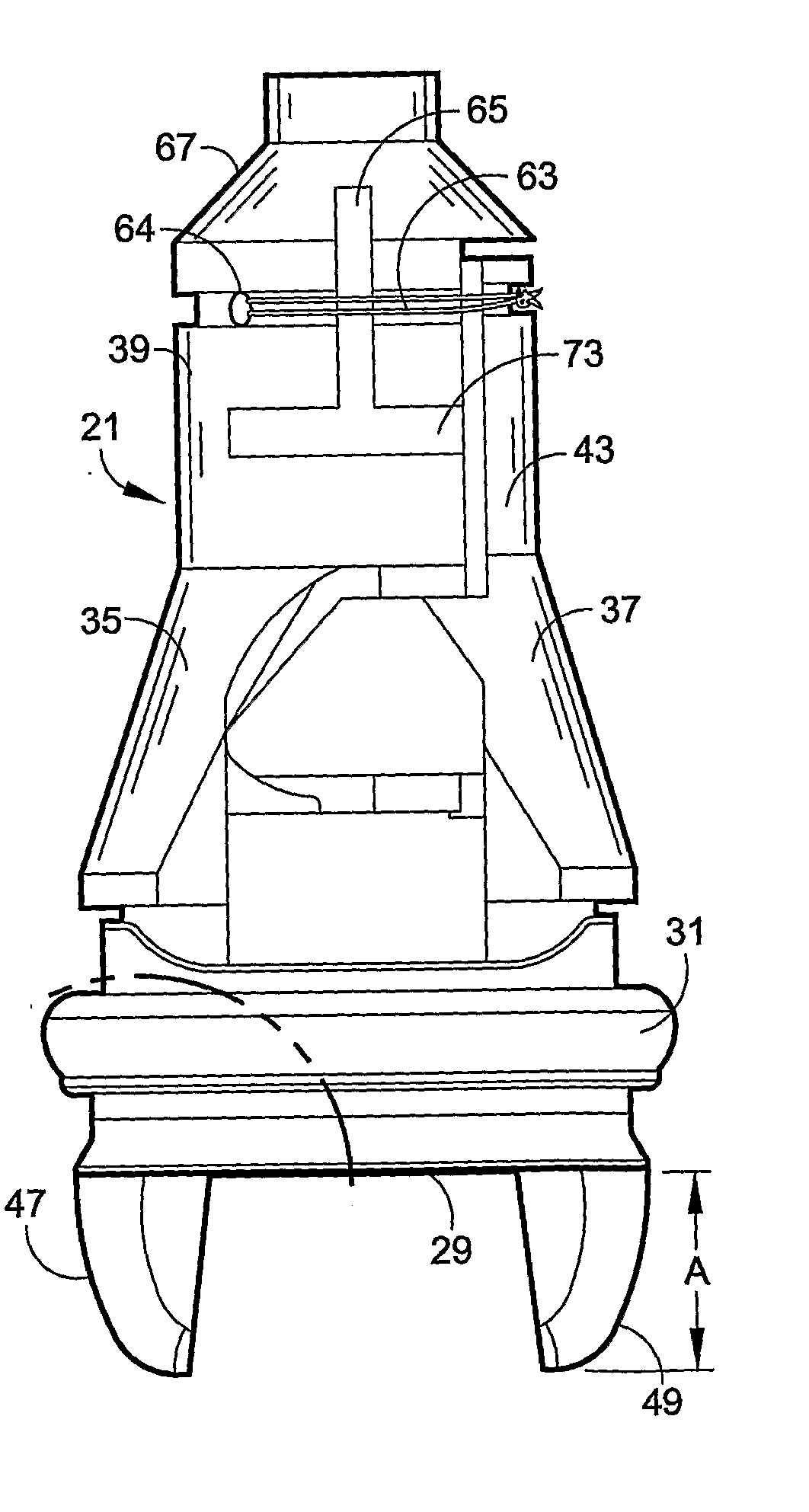
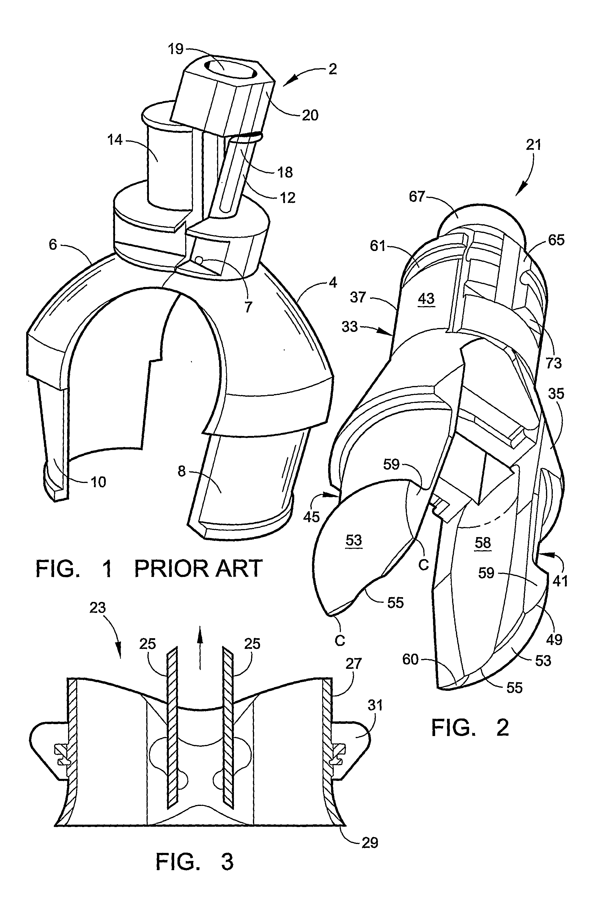
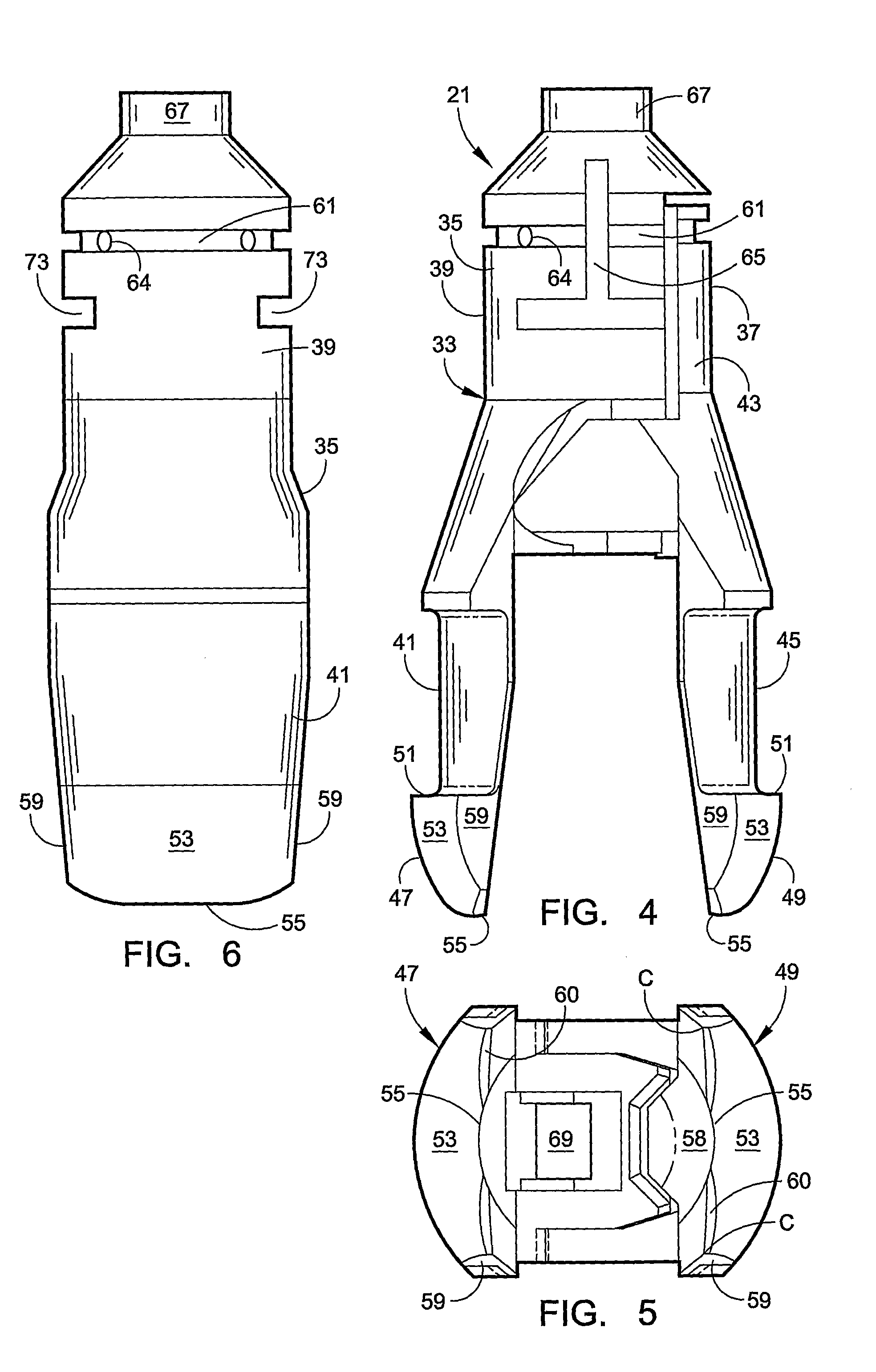
[0026] The invention provides a device 21 which serves as a holder-inserter for implanting a mechanical heart valve prosthesis in an annulus in the human heart. The principles embodied in the device 21 are effective in creating a useful holder-inserter suited for implanting a wide variety of mechanical heart valves, particularly bileaflet heart valves; however, the preferred embodiment of the device that is shown in the drawings is proportioned and shaped to facilitate the implantation of the On-X heart valve 23, a cross-sectional view of which is illustrated in FIG. 3. This valve 23 employs a pair of leaflets 25 that are pivotally mounted on a valve body or orifice ring 27, as described in detail in the earlier mentioned U.S. Pat., which valve body 27 has an outwardly flaring entrance end 29. The illustrated valve 23 is designed to be inserted as an aortic valve replacement where it will be positioned so that the concave, generally toroidal exterior surface of the curved entrance e...


PUM


Abstract

A heart valve holder-inserter (21, 121) is designed to facilitate easy implantation of a mechanical heart valve pros-thesis (23, 123). This holder-inserter, at its distal end, incorporates a pair of diametrically opposed guide members (47, 49, 81, 147, 149) which extend well beyond the leading edge of the prosthesis and which have exterior surfaces (53, 83, 153) of substantial dimension that are smoothly curved and proportioned so as to slowly spread the tissue annulus in order to facilitate easy entrance thereinto of the leading edge portion of the mechanical valve body.

Description

[0001] This application claims priority from U.S. Provisional Patent Application Serial No. 60 / 650,778, filed Jan. 27, 2005.[0002] The present invention relates to a device for holding and inserting a mechanical heart valve prosthesis and more particularly to a device of this type which facilitates the insertion of an aortic heart valve. BACKGROUND OF THE INVENTION [0003] The use of surgically implanted mechanical heart valves has become widespread throughout the world and even routine in many countries. There are a variety of mechanical heart valves that have become well-accepted for use in the United States, Europe and Japan as well as in other countries throughout the world, one of which is sold as the On-X heart valve by Medical Carbon Research Institute, LLC, the assignee of this application. This mechanical heart valve prosthesis is shown in U.S. Pat. Nos. 5,545,216, 5,641,324, 5,772,694 and 5,908,452, for example. [0004] Special tools have been developed to assist in the impl...

Claims


Application Information

Patent Timeline
Patent Type & Authority Applications(United States)
IPC IPC(8): A61F2/24
CPCA61F2/2427
Inventor BOKROS, JACK C.STUPKA, JONATHAN C.WAITS, C. THOMAS
Owner VALVE SPECIAL PURPOSE CO
Why Eureka
Try Eureka