Vacuum-insulated pipe

a technology of thermal insulation piping and vacuum insulation, which is applied in the direction of flexible pipes, pipes, pipe protection, etc., can solve the problems of reducing the service life of the vacuum evacuation device, imposing restrictions on the space, and affecting the work efficiency so as to facilitate the set-in work of the thermal insulation piping and reduce the evacuation resistance

Inactive Publication Date: 2006-08-22
SUMITOMO ELECTRIC IND LTD +1
View PDF16 Cites 34 Cited by
  • Summary
  • Abstract
  • Description
  • Claims
  • Application Information

AI Technical Summary

Benefits of technology

[0007]By orienting the evacuation port parallel with the longitudinal direction of the thermal insulation piping, no radial projection from the periphery of the thermal insulation piping is provided. This allows smooth insertion of the thermal insulation piping into a pipeline or equivalent. In addition, in comparison with the conventional thermal insulation piping that needs some protection for such a radially projecting evacuation port at the set-in work, the thermal insulation piping of the present invention can eliminate the need to give some protection to the evacuation port. This can facilitate the set-in work of the thermal insulation piping.
[0008]It is preferable that the thermal insulation piping includes a plurality of evacuation ports. The provision of the plurality of evacuation ports can provide reduced evacuation resistance to provide more effective evacuation.

Problems solved by technology

As a result of this, when the thermal insulation pipe is set, for example, in a pipeline or a narrow space, the evacuation port itself becomes an obstacle as a projecting part and thus imposes restrictions on the space where the thermal insulation pipe may be set in.
Further, when this thermal insulation pipe is set in, the projecting evacuation port, or a tip portion of the evacuation port to be connected with the vacuum evacuation device, in particular, is vulnerable to damage.

Method used


Image

  • Vacuum-insulated pipe
  • Vacuum-insulated pipe
  • Vacuum-insulated pipe

Examples


Embodiment Construction

[0015]In the following, an embodiment of the present invention will be described.

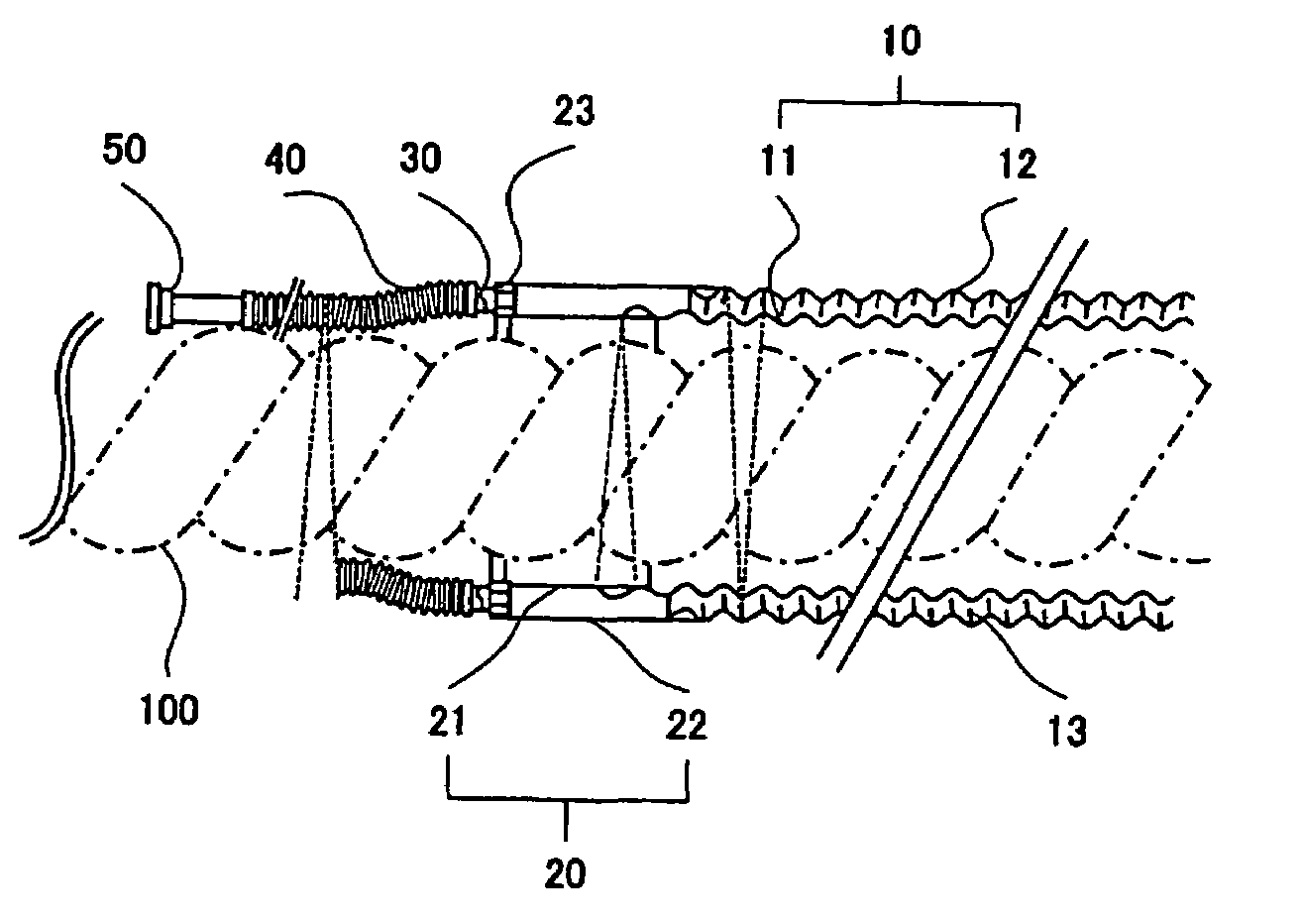
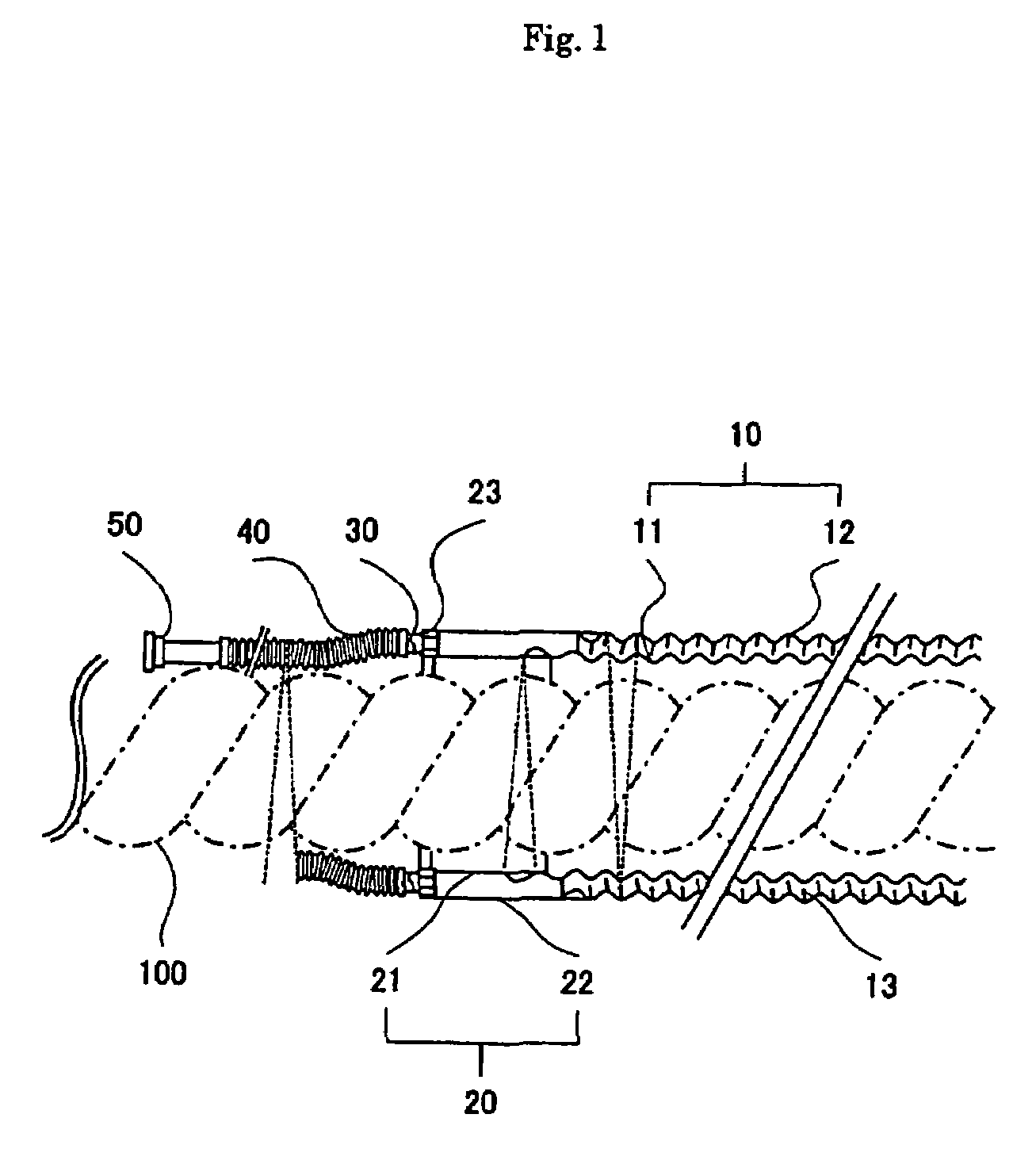
[0016]FIG. 1 is a partial vertical section of a thermal insulation piping of the present invention. It is to be noted here that the thermal insulation piping used for a superconducting cable is illustrated as an example of the present invention.

[0017]The thermal insulation piping of the present invention has the construction wherein a thermal insulation tube 10 comprising an inner tube 11 and an outer tube 12 and having a vacuum layer therebetween is connected to a straight double tube 20 at an end thereof, and evacuation ports 30 are formed in an end face of the double tube 20. Further, the evacuation ports 30 are connected to flexible pipes 40.

[0018]The inner tube 11 and the outer tube 12 are preferably in the form of a corrugated tube formed of aluminum alloy or equivalent. The so-called “super-insulation” which is in the form of a laminated layer 13 comprising polypropylene mesh and aluminum foil is...


PUM


Abstract

To provide a thermal insulation piping with no radially projecting part from a periphery thereof, so as to facilitate insertion of the thermal insulation piping into a pipeline or equivalent. In a thermal insulation tube 10 having a vacuum layer between an inner tube 11 and an outer tube 12, an evacuation port 30 for vacuum evacuation is oriented parallel with a longitudinal direction of the thermal insulation piping at an end of the thermal insulation tube 10. This construction can produce the thermal insulation tube 10 with no radially projecting part from a periphery thereof, thus providing improved workability when the thermal insulation piping is contained in the pipeline or equivalent. Further, a flexible pipe(s) 40 is / are preferably connected to the evacuation port(s) 30. This can allow increased positional tolerances in the connection of the evacuation port(s) to a vacuum evacuation device.

Description

TECHNICAL FIELD[0001]The present invention relates to a thermal insulation piping having a double tube structure. More particularly, the present invention relates to a thermal insulation piping that provides no projecting part around an outside thereof to facilitate insertion of the thermal insulation piping in a pipeline.BACKGROUND ART[0002]A thermal insulation pipe, such as a water-supply pipe, is generally known from the technology disclosed by Japanese Patent Laid-open (Unexamined) Publication No. 2000-81192. This has the construction wherein a vacuum layer is formed in an interspace of a double tube 60 comprising an inner tube 61 and an outer tube 62, as shown in FIG. 2. The space between the inner and outer tubes is provided with a hollow fiber membrane unit 70 and minute hollow glass beads 80. The hollow fiber membrane unit 70 suppresses collision of gas molecules in that space. The minute hollow glass beads 80 provide increase of heat transfer distance. The combination of th...

Claims


Application Information

Patent Timeline
Patent Type & Authority Patents(United States)
IPC IPC(8): F16L59/06F16L9/14
CPCF16L59/065
Inventor WATANABE, MICHIHIKOTAKAHASHI, YOSHIHISAMATSUO, KIMIYOSHIHONJO, SHOICHIMIMURA, TOMOOAIBA, TERUMITSU
Owner SUMITOMO ELECTRIC IND LTD
Why Eureka
Try Eureka