Reagent injection apparatus and method of producing the same

a technology of reagent injection and apparatus, which is applied in the direction of catheters, coatings, other medical devices, etc., can solve the problems of insufficient effect to achieve the effect of smooth puncture operation of needles, and achieve the effect of simple structure, reduced lumens, and high supporting force of main tubes

Active Publication Date: 2007-06-07
KATOH OSAMU +1
View PDF58 Cites 33 Cited by
  • Summary
  • Abstract
  • Description
  • Claims
  • Application Information

AI Technical Summary

Benefits of technology

[0011] Here, in view of the background described above, it is an object in an embodiment of the present invention to provide a reagent injection apparatus that permits more reliable and smoother puncturing of a specified position in body tissue to a specified depth using the tip of the needlelike tubular body, and also achieves diameter or size reduction in an advantageous manner. It is another object in an embodiment of the present invention to provide a method of producing such reagent injection apparatus in an advantageous manner.
[0013] To be specific, a reagent injection apparatus conforming to an embodiment allows, when the main tube is inserted into a blood vessel or other tubular organ branching into two parts, the tip of the needlelike tubular body to puncture a specified body tissue to inject reagent, by inserting the first guide wire into one of the two branching tubular organs and the second guide wire into the support tube to have the support tube support the wire, and then puncturing the body tissue with the needlelike tubular body while the second guide wire and support tube are both inserted into the other tubular organ. This way, the reactive force generated when the tip of needlelike tubular body punctures the body tissue or any other acting force resulting from twisting or other movement of the needlelike tubular body (hereinafter referred to as “reactive force of puncturing”) can be received in an advantageous manner by not only the first guide wire and second guide wire, but also by the support tube.
[0015] For the aforementioned reasons, such apparatus conforming to an embodiment suppresses in a more reliable manner any movement or rotation of the main tube around the axis due to the reactive force of puncturing that generates when the body tissue is punctured with the needlelike tubular body. As a result, even a large reactive force can be reliably received when puncturing the cardiac muscle and other relatively hard lesions with the needlelike tubular body, and thus in situations where the main tube must be stably positioned in the blood vessel, a specified position in body tissue can be punctured to a desired depth in a smooth manner.
[0016] In addition, a apparatus conforming to an embodiment virtually eliminates the need for a balloon as installed on the main tubes of conventional apparatuses, because the apparatus under an embodiment can reliably and sufficiently receive the reactive force of puncturing using the two guide wires and support tube, and is therefore able to exhibit higher supporting force of the main tube against the reactive force of puncturing. This means that the balloon lumen normally provided in the main tube to supply liquid to inflate the balloon can also be eliminated.
[0017] Moreover, in a reagent injection apparatus conforming to an embodiment all of its openings on distal side and proximal side in the first guide wire lumen and second guide wire lumen open in the distal section of the main tube. Therefore, except for this distal side a greater part of the remaining section of the main tube has a simple structure in which only a needlelike tubular body lumen is provided in its interior. This virtually reduces the number of lumens in the main tube.
[0018] For the aforementioned reasons, a reagent injection apparatus conforming to an embodiment not only permits smoother insertion into the patient's body through the use of a main tube of smaller diameter or size, but it also allows reagent to be injected more accurately into a lesion or other part of body tissue because the apparatus can be positioned stably in a desired position inside the patient's body to perform puncturing operation. Furthermore, a reagent injection apparatus conforming to an embodiment also provides an advantage of ensuring more stable blood flows, when the apparatus is used in a blood vessel, owing to the smaller diameter or size of the main tube.

Problems solved by technology

In the use of these conventional reagent injection apparatuses, however, it is difficult, simply by inserting the two guide wires into the two branching blood vessels, to sufficiently suppress movement or rotation of the main tube around the axis caused by the reactive force generated when the needle punctures the body tissue or by any other acting force resulting from twisting or other movement of the needle.
For the reason, in some cases sufficient effect cannot be obtained to operate the needle to smoothly puncture a specified position in body tissue to a desired depth, particularly in situations where the main tube must be stably positioned in the blood vessel to perform puncture operation, such as when puncturing the cardiac muscle or other relatively hard lesions with the needle.

Method used


Image

  • Reagent injection apparatus and method of producing the same
  • Reagent injection apparatus and method of producing the same
  • Reagent injection apparatus and method of producing the same

Examples


Embodiment Construction

[0048] The present invention will be explained with reference to preferred embodiments and drawings. However, the preferred embodiments and drawings are not intended to limit the present invention.

[0049] The present invention can be preferably implemented in the following embodiments:

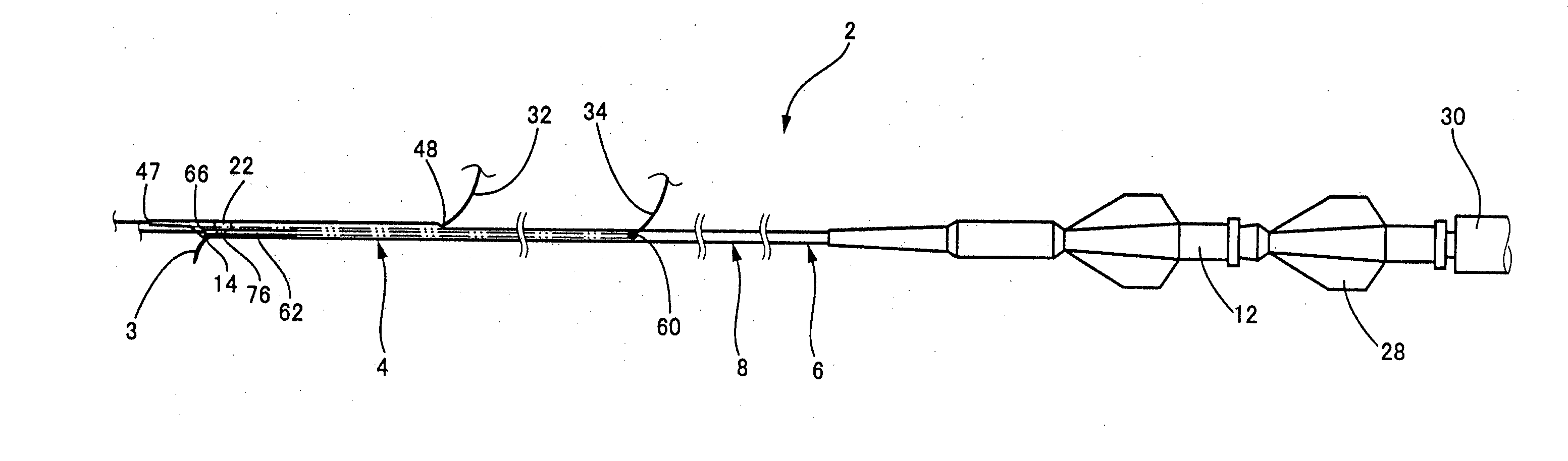
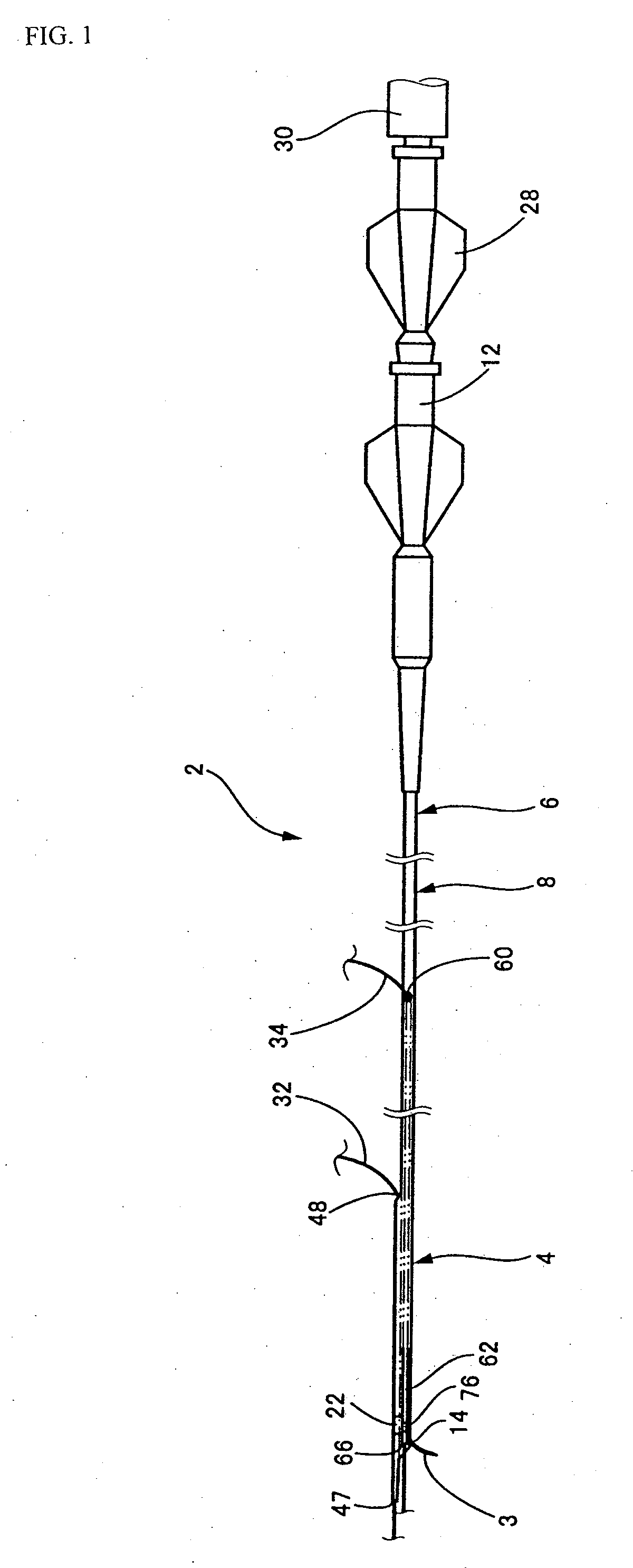
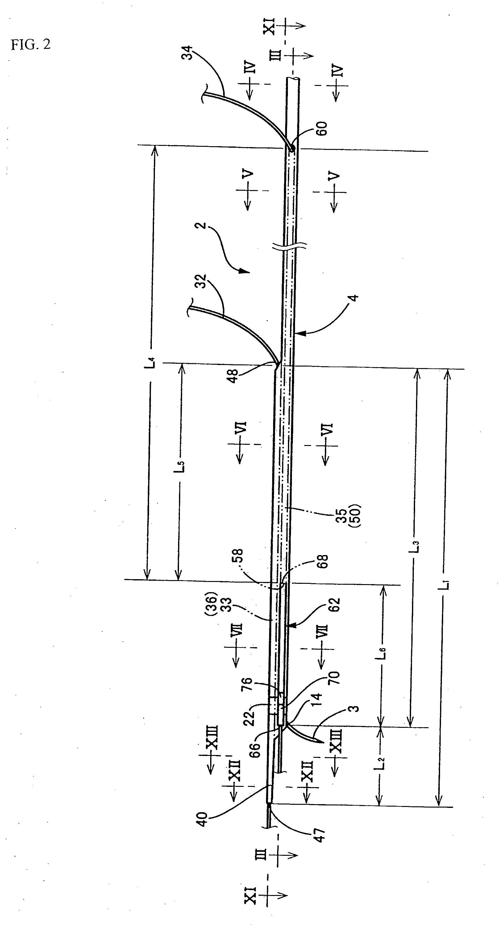
[0050] 1) A reagent injection apparatus characterized by comprising: (a) a main tube having flexibility, providing a needlelike tubular body lumen in a manner extending in an axial direction, and inserted into the patient's body; (b) a needlelike tubular body made of a flexible thin tube having an interior hole through which specified reagent can flow; wherein the needlelike tubular body is inserted into the needlelike tubular body lumen of the main tube in a manner movable in the axial direction; and wherein its tip section is projected outward from a projection hole provided in a distal section of the main tube to puncture specified tissue in the patient's body, in order to inject the reagent into t...


PUM

PropertyMeasurementUnit
total lengthaaaaaaaaaa
lengthaaaaaaaaaa
thicknessaaaaaaaaaa

Abstract

A structure includes a main tube 2 that contains a needlelike tubular body lumen 10 through which a needlelike tubular body 3 is inserted, with a distal section 4 of the main tube 2 having a first guide wire insertion section 33 and second guide wire insertion section 35, respectively containing a first guide wire lumen 38 and second guide wire lumen 52 through which a first guide wire 32 and second guide wire 34 are inserted. This structure further has a support tube 62 whose tip remains a free end, wherein this support tube 62 accepts a part of the second guide wire 34 extending out of the second guide wire lumen 52 and thereby supports the second guide wire insertion section 35.

Description

BACKGROUND OF THE INVENTION [0001] 1. Field of the Invention [0002] The present invention relates to a reagent injection apparatus for injecting specified reagents into lesions and other locations in body tissues, as well as a production method of reagent injection apparatus thereof. [0003] 2. Description of the Related Art [0004] Traditionally, various treatments, inspections, procedures and other medical manipulations have been conducted by inserting medial apparatuses, such as catheters, into blood vessels, gastrointestinal tract, urinal tract, and various other tubular organs and tissues in the patient's body. In recent years, treatments and other procedures are also carried out wherein reagent injection apparatuses such as reagent injection catheters are used to inject specified reagents into lesions in body tissues (Japanese Patent Laid-open No. 2001-299927 for an example). [0005] These reagent injection apparatuses used in treatments and other procedures performed by means of...

Claims


Application Information

Patent Timeline
Patent Type & Authority Applications(United States)
IPC IPC(8): A61M25/00
CPCA61M25/0009A61M25/0045A61M25/005A61M25/007A61M25/0071A61M25/0084A61M25/0108A61M25/04A61M2025/0092A61M2025/0096A61M2025/018A61M2025/0183A61M25/01A61M25/09A61M29/00A61M31/00
Inventor KATOH, OSAMUTSUCHIKANE, ESTUOKUREHA, ATSUSHIWATANABE, NOBUYOSHI
Owner KATOH OSAMU
Why Eureka
Try Eureka