Recording apparatus with removable stacker

a stacker and recording apparatus technology, applied in the field of stacker, can solve the problems of abrasion and so on on the recording surface, and the process of attaching such a large stacker is extremely complicated

Inactive Publication Date: 2011-08-16
SEIKO EPSON CORP
View PDF11 Cites 34 Cited by
  • Summary
  • Abstract
  • Description
  • Claims
  • Application Information

AI Technical Summary

Benefits of technology

[0008]An advantage of some aspects of the invention is to provide a recording apparatus to which a large-sized stacker can be attached with ease.
[0014]By employing such a configuration, according to the invention, when one of the grounded frames is moved by applying an external force from thereabove, the other grounded frame also moves at the same time due to the effects of the frame structure, and it is thus possible to easily move the second engagement portion by operating the grounded frame on the opposite side of the grounded frame in which the second engagement portion is provided.
[0016]By employing such a configuration, according to the invention, the regulation portion regulates the amount by which the stacker is depressed when the external force is applied to the stacker; as a result, the insertion section of the guidance portion and the second engagement portion are at the same height when the stacker has been depressed, making it possible to smoothly insert the second engagement portion into the guidance portion.
[0018]By employing such a configuration, according to the invention, it is easy to insert the second engagement portion into the insertion section, and it is possible to smoothly guide the second engagement portion along the guidance portion.

Problems solved by technology

With a rear type stacker, the recording surface side of the paper, onto which the recording process has been carried out, rubs against the stacker as the paper is stacked, and thus there is the concern that abrasions and so on will occur in the recording surface.
Thus, in the past, a system in which the stacker is attached to the ink jet printer only when the stacker is necessary has been employed, but this too has been problematic in that attaching such a large-size stacker is an extremely complicated process.

Method used


Image

  • Recording apparatus with removable stacker
  • Recording apparatus with removable stacker
  • Recording apparatus with removable stacker

Examples


Embodiment Construction

[0031]An embodiment of a recording apparatus according to the invention will be described hereinafter with reference to the drawings. It should be noted that in the drawings used in the following descriptions, the scale of the various constituent elements has been changed in order to achieve sizes that are more visibly recognizable. This embodiment discusses, as the recording apparatus according to the invention, a large-format ink jet printer (LFP), which is capable of, for example, performing printing processes using comparatively large-size recording paper (for example, JIS A1, JIS B1, and so on) as the recording medium.

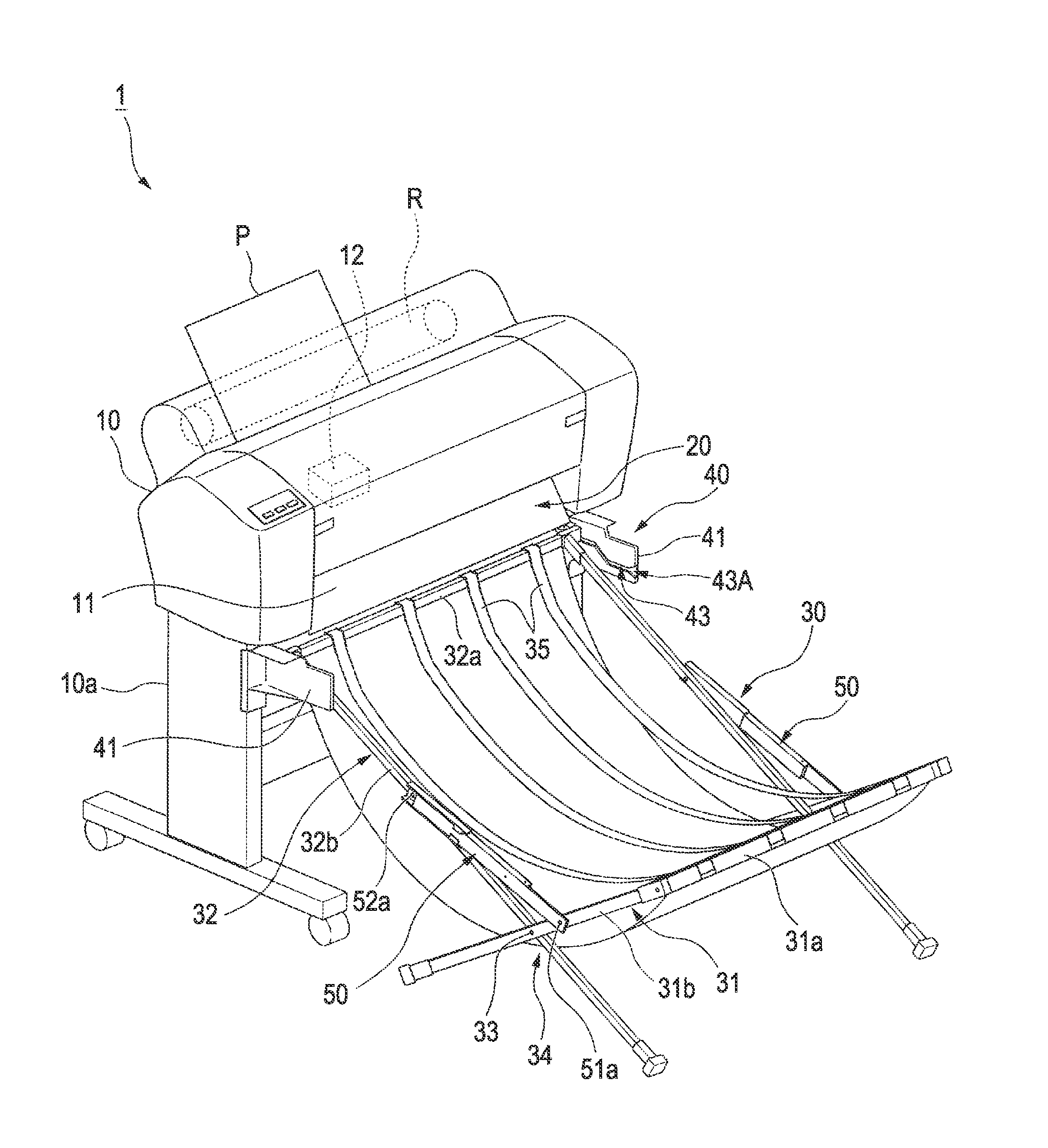
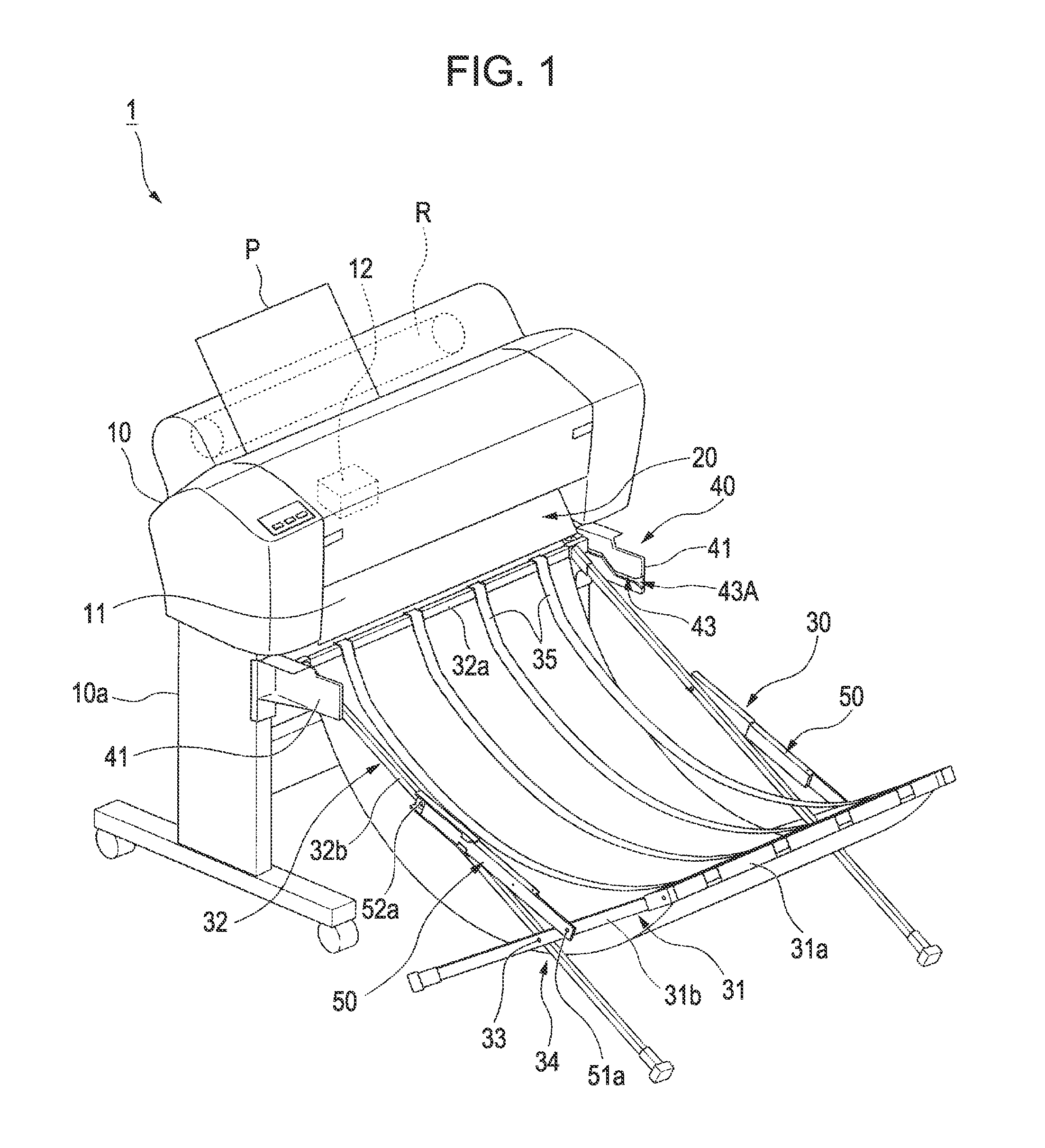
[0032]FIG. 1 is a perspective view of an ink jet printer 1 according to an embodiment of the invention.

[0033]The ink jet printer 1 includes a main printer unit 10 that performs a printing process on recording paper P. The main printer unit 10 is supported at a predetermined height by a pair of leg portions 10a. The main printer unit 10 includes a transport path 11...


PUM


Abstract

A recording apparatus has a stacker that receives a discharged recording medium. An engagement mechanism removably attaches the stacker to a discharge section of the apparatus and includes a first engagement portion provided in the discharge section; a second engagement portion, on the stacker, that engages with the first engagement portion; and a guidance portion that guides the second engagement portion into the first engagement portion and extends in an upward direction. The second engagement portion is biased, by a biasing unit on the stacker, in the upward direction so as to move in the guidance portion. When an external force that opposes the biasing force is applied to the stacker and that external force is released, the second engagement portion rises due to the biasing force, is guided by the guidance portion, and engages with the first engagement portion.

Description

CROSS-REFERENCE TO RELATED APPLICATIONS[0001]Japanese Patent Application No. 2009-180370 is hereby incorporated by reference in its entirety.BACKGROUND[0002]1. Field of Invention[0003]The present invention relates to recording apparatuses.[0004]2. Description of Related Art[0005]Ink jet printers, such as that disclosed in JP-A-2008-281549 and described below, are known as recording apparatuses that carry out recording processes on a recording medium.[0006]JP-A-2008-281549 discloses a large-format ink jet printer (LFP), which is capable of, for example, performing printing processes using comparatively large-size recording paper (for example, JIS A1, JIS B1, and so on) as the recording medium. This ink jet printer includes a recording head capable of moving back and forth in a sub direction, which is orthogonal to the transport path of the recording paper, and the printing process is carried out by ejecting ink onto the recording paper from this recording head. Printing paper that ha...

Claims


Application Information

Patent Timeline
Patent Type & Authority Patents(United States)
IPC IPC(8): B65H31/04
CPCB65H31/02B65H31/22B65H2801/36B65H2701/11312B65H2801/12B65H2402/344B65H2402/30
Inventor SAITO, YUSUKEKATO, JUNYA
Owner SEIKO EPSON CORP
Why Eureka
Try Eureka