Caster assembly with drawn kingpin rivet

a kingpin rivet and caster technology, applied in the field of caster assembly held together by a kingpin rivet, can solve the problems of even more complexdies required to form tempered stainless, and achieve the effects of simplified assembly, reduced stress, and high stress

Inactive Publication Date: 2006-06-27
SORENSEN MARK C
View PDF14 Cites 14 Cited by
  • Summary
  • Abstract
  • Description
  • Claims
  • Application Information

AI Technical Summary

Benefits of technology

[0016]The present invention is a caster assembly that employs a unique combination of materials and geometry to arrive at a product that is durable, highly corrosion resistant, light-weight, and exhibits excellent passive shock absorbing qualities. All of the sheet metal parts can be efficiently stamped to arrive at an economical cost that is half that of stainless steel casters and very competitive with low carbon steel casters of reasonable quality. A unique drawn and curled kingpin rivet permanently retains the assembly. The end product is a caster assembly of exceptional quality and durability that can be tailored to handle anything from light to heavy-duty applications.
[0017]The caster assembly generally comprises an upper race, a lower race, a wheel chassis sandwiched between these parts, a thrust bearing assembly, and a proximally located drawn kingpin rivet for permanent retention. The upper race may be substantially circular and flat with a formed bearing groove that circumscribes the outer perimeter. Similarly, the lower race may have a flat inner portion and a drawn cylindrical portion circumscribed by a formed bearing groove. The thrust bearing assembly generally comprises an upper and lower set of ball bearings that reside in the raceway bearing grooves, a spacer and a shim for proper bearing spacing, and one or more o-ring seals that protect it from environmental contamination. The caster assembly may combine these and other elements to reliably aid in the movement of heavy equipment. Additionally, a mounting plate may be included to facilitate attachment to the supported equipment. The mounting plate may be a rectangular plate with mounting holes for screws and the like that attaches to a frame member of the unit. The mounting plate may also be a corner bracket for ease of attachment to the corners of equipment. Alternatively, the mounting plate may be eliminated altogether as the device may be attached to the equipment with a standard fastener that passes through the hollow center of the drawn kingpin rivet.

Problems solved by technology

The dies required to form tempered stainless are even more complex than ordinary stainless dies requiring close attention to detail and the highest level of tool and die expertise.

Method used


Image

  • Caster assembly with drawn kingpin rivet
  • Caster assembly with drawn kingpin rivet
  • Caster assembly with drawn kingpin rivet

Examples


Embodiment Construction

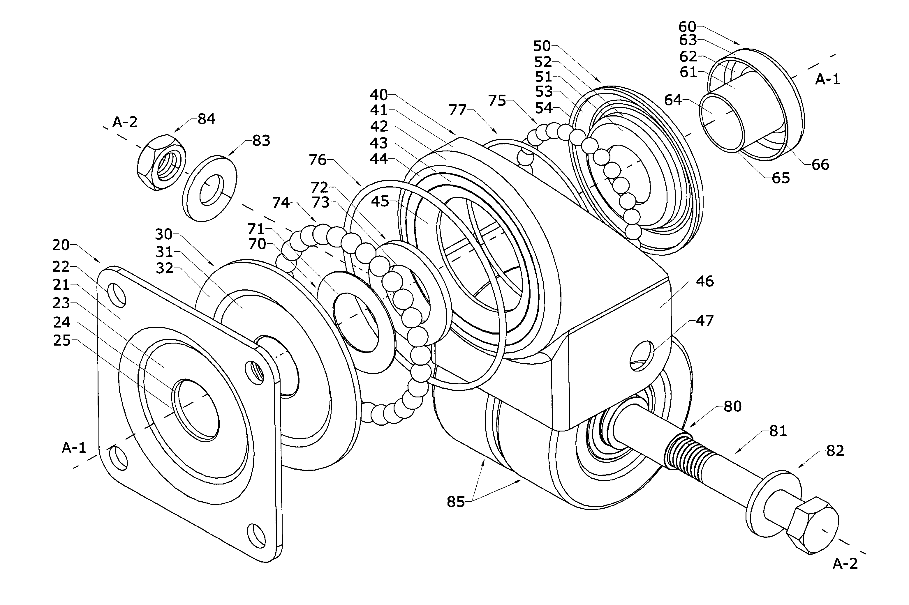
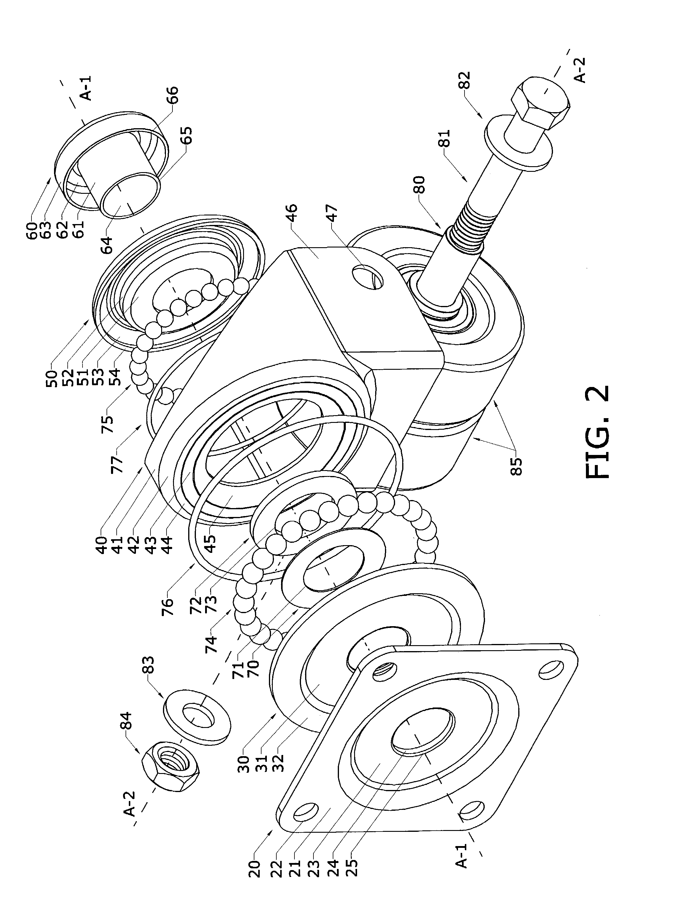
[0043]A preferred embodiment of the present invention is a caster assembly that generally comprises a mounting plate, an upper race, a wheel chassis, a lower race, and a thrust bearing assembly all permanently retained by a proximally located double drawn kingpin rivet. The thrust bearing assembly generally comprises an upper and lower set of ball bearings, a shim and spacer, and one or more o-ring seals. The caster assembly may combine these and other elements to reliably aid in the movement of heavy equipment while providing exceptional passive shock absorption, corrosion resistance, and light weight.

[0044]FIGS. 1–4 show a first embodiment of the caster assembly 10 with a double drawn kingpin in accordance with the present invention. All structural parts of the device may be manufactured as sheet metal stampings from various stainless steels. The mounting plate 20 may be formed from an annealed stainless and is generally designed to mate with and affix to the underside of a frame ...


PUM


Abstract

A caster assembly including a unique drawn kingpin rivet formed of stainless steel or other material of appropriate toughness which compressively holds the components of the caster assembly together.

Description

BACKGROUND OF THE INVENTION[0001]Casters, which generally comprise a wheel or the like swivel-mounted on a chassis, are used in many industrial applications. They can be ordered with different configurations, sizes, materials, and load capacities. This invention relates a caster assembly held together by a drawn kingpin rivet. The assembly exhibits several unique qualities, including the ability to passively absorb shock to a much greater extent than similar devices.[0002]There are three general categories of casters: furniture, industrial, and specialty. Furniture casters are found on all types of office and household items. They are the cheap to produce, as they are largely constructed from injection molded plastic, but they suffer from a relatively low load capacity (<100 lbs.)[0003]Industrial casters are generally manufactured by an economical stamping or cold forging process with secondary welding operations. They include light-duty casters, such as those found on shopping c...

Claims


Application Information

Patent Timeline
Patent Type & Authority Patents(United States)
IPC IPC(8): A47B91/00B60B33/00
CPCB60B33/0002B60B33/0007B60B33/0018B60B33/0028B60B33/0042B60B33/0057B60B33/0068B60B33/0073B60B33/0049Y10T16/1857Y10T16/184Y10T16/1867F16C19/10F16C33/588F16C2326/02
Inventor SORENSEN, MARK C.
Owner SORENSEN MARK C
Why Eureka
Try Eureka