
Stamping process and automatic stamping equipment for the main body of the switchgear chassis

A thin plate stamping and chassis car technology, which is applied in the direction of metal processing equipment, manufacturing tools, feeding devices, etc., can solve the problems of safety hazards, hand cuts, etc.

Active Publication Date: 2017-10-17
青田薪侨电器科技有限公司
View PDF6 Cites 0 Cited by
  • Summary
  • Abstract
  • Description
  • Claims
  • Application Information

AI Technical Summary

Problems solved by technology

[0002] The switchgear chassis is an important part of the switchgear. Each punching hole on the traditional switchgear chassis is formed by a punching machine at one time. When transporting the switch cabinet chassis, the burrs in the area of ​​the chassis are facing outwards, which can easily cut people's hands and cause safety hazards. There is an urgent need in the market for a machine that can reverse the front and back of different mounting holes on the switch cabinet chassis. equipment

Method used


Image

  • Stamping process and automatic stamping equipment for the main body of the switchgear chassis
  • Stamping process and automatic stamping equipment for the main body of the switchgear chassis
  • Stamping process and automatic stamping equipment for the main body of the switchgear chassis

Examples


Embodiment 1

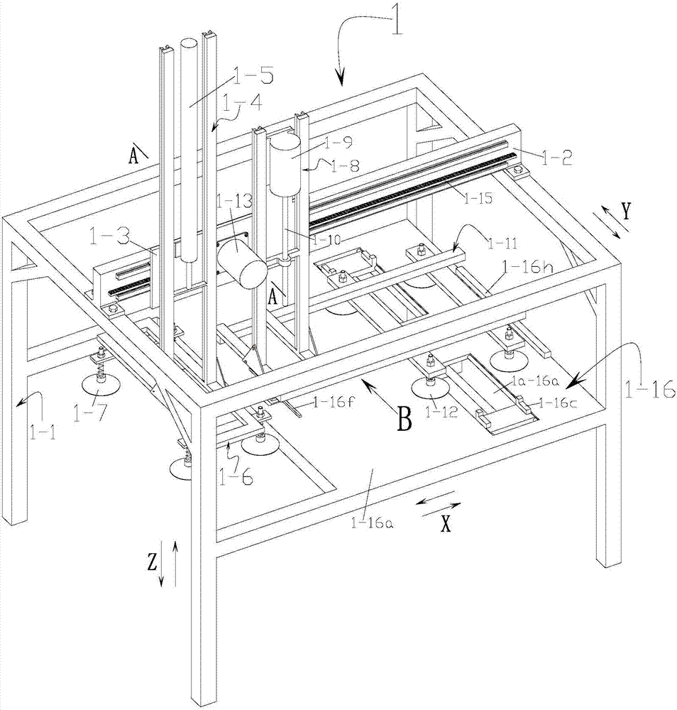
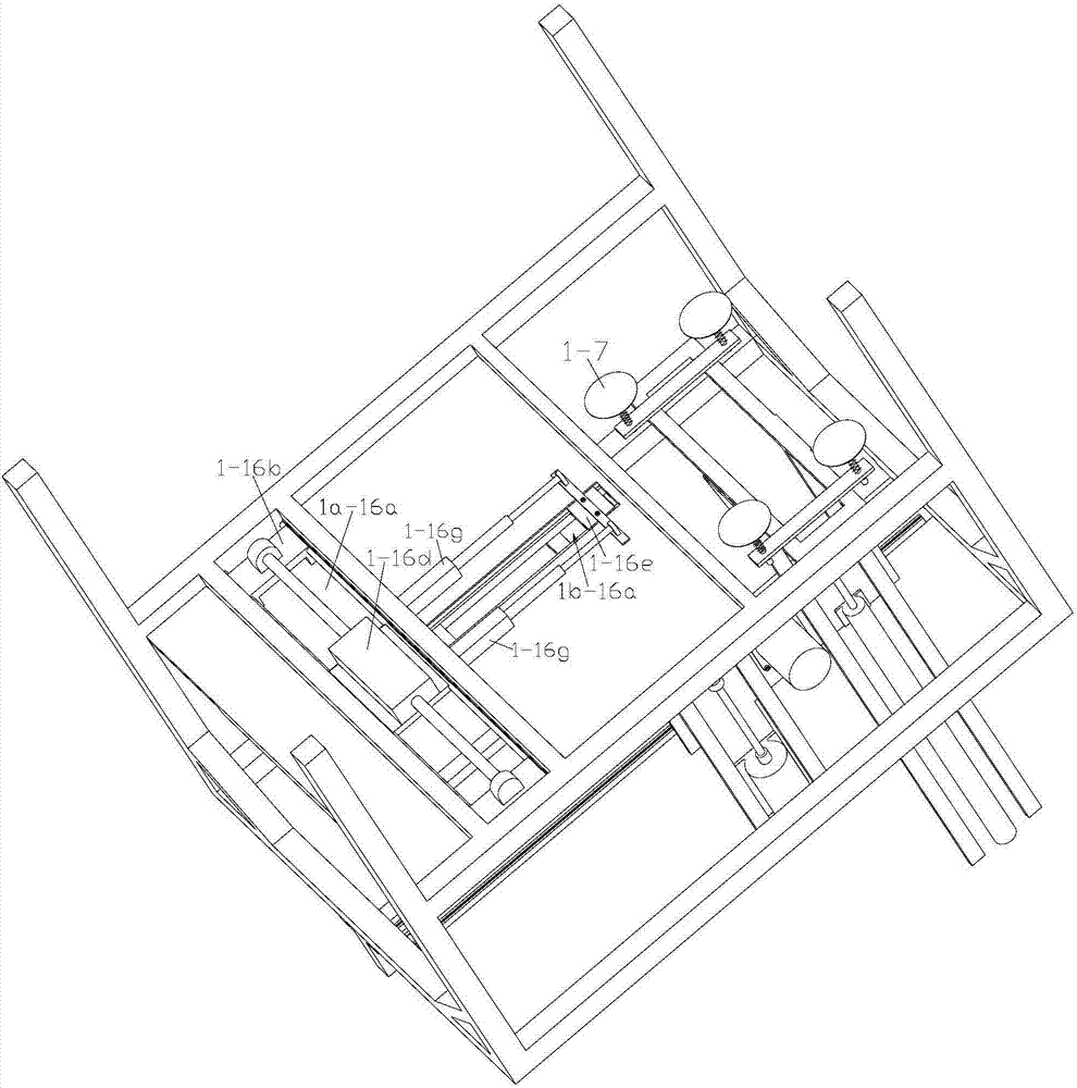
[0045] Refer to attached figure 1 , 2 , 4, 5, 6, 7, 8, 9, 10, 11, 13, 14, 15, 16, 17, 18, 19, 20, 21:

[0046] A stamping process for a main body of a switchgear chassis, comprising the following steps:

[0047] A. Feeding: Place the thin plate raw material 8 on the raw material placement table 7, start the first cylinder 1-5 to drive the square horizontal frame 1-6 to move down, until the vacuum suction cup 1-7 sucks the thin plate raw material 8, the first cylinder 1 -5 drives the thin plate raw material 8 to move up to the initial position of the square horizontal frame 1-6, and then the servo motor two 1-13 drives the moving plate one 1-3 to move to the right, and brings the thin plate raw material 8 to the correction mechanism one 1-16 Above, then the first cylinder 1-15 drives the square horizontal frame 1-6 to move down for a short distance, the vacuum suction cup 1-7 inflates to place the sheet material 8 on the support plate 1-16a, and starts the first multi-stage c...

Embodiment 2

[0062] Refer to attached Figure 12 : This switchgear chassis car main body thin plate automatic stamping equipment is different from embodiment one in that: drive mechanism 3-21 includes servo motor nine 3-21c and reversing reducer 3-21 fixed on the support frame 3-19 21d, the rotating shaft of servo motor nine 3-21c is fixed on the input shaft place of reversing reducer 3-21d, and the output shaft of reversing reducer 3-21d is fixed with gear six 3-21e, gear six 3-21e and gear four 3-18 gear meshing. The principle of its stamping thin plate raw material 8 is the same as that of Embodiment 1, except that the power source of the drive mechanism 3-21 utilizes servo motor 9 3-21c, reversing reducer 3-21d and gear 6 3-21e to drive gear 4 3-18 Rotate and drive the rotating rod 3-14 to rotate 180° clockwise.


PUM


Abstract

A stamping technique for a sheet of a switch cabinet chassis truck main body comprises the following steps of A, feeding, B, primary stamping, C, output reversing, D, secondary feeding, E, secondary stamping, and F, output. Automatic stamping equipment of the sheet of the switch cabinet chassis truck main body sequentially comprises a feeding device of the sheet of the switch cabinet chassis truck main body, a first stamping device, a discharging and reversing device of the sheet of the switch cabinet chassis truck main body, a feeding device of the sheet of the switch cabinet chassis truck main body, a second stamping device and an output device of the sheet of the switch cabinet chassis truck main body from left to right. By the adoption of the stamping technique for the sheet of the switch cabinet chassis truck main body and the automatic stamping equipment of the sheet of the switch cabinet chassis truck main body, installation holes located in the front side and the back side of the sheet of the switch cabinet chassis truck main body can be stamped rapidly and automatically, the efficiency is high, and the stamping technique and the automatic stamping equipment are worthy of application and popularization.

Description

technical field [0001] The invention relates to a processing technology and processing equipment, in particular to a stamping process and automatic stamping equipment for the thin plate of the main body of a switch cabinet chassis. Background technique [0002] The switchgear chassis is an important part of the switchgear. Each punching hole on the traditional switchgear chassis is formed by a punching machine at one time. When transporting the switch cabinet chassis, the burrs in the area of ​​the chassis are facing outwards, which can easily cut people's hands and cause safety hazards. There is an urgent need in the market for a machine that can reverse the front and back of different mounting holes on the switch cabinet chassis. equipment. Contents of the invention [0003] The present invention aims to solve the above-mentioned shortcomings of the prior art, and provides a switchgear chassis vehicle main body thin plate stamping process and automatic stamping equipmen...

Claims


Application Information

Patent Timeline
Patent Type & Authority Patents(China)
IPC IPC(8): B21D28/26B21D43/18B21D45/00
CPCB21D28/26B21D43/18B21D45/003
Inventor 水寿松翁迪院张晓明
Owner 青田薪侨电器科技有限公司
Learn More