Device and method for tensioning a screen on a screen printing frame

a technology of screen printing and tensioning device, which is applied in the direction of printing, door/window protective device, synthetic resin mesh, etc., can solve the problems of squeegee injury, joint loss, and joint loss between two different types of screens, so as to prevent physical breakdown

Inactive Publication Date: 2007-10-23
KASUYA FURETABU
View PDF49 Cites 12 Cited by
  • Summary
  • Abstract
  • Description
  • Claims
  • Application Information

AI Technical Summary

Benefits of technology

[0016]Also, no screen frame has been proposed in which the screen frame arranged variable in length of its frame sides is improved in combination with screen hooking tools joined with a screen for spreading the screen, controlling tension on the screen, or allowing the screen hooking tools to be attached and detached with ease.
[0038]As the screen frame is simply deflected for minimum adjustment, it can be prevented from physical breakdown.

Problems solved by technology

However, a joint between two different material screens, such as a metal sheet and a synthetic resin mesh, or between two different types, such as a mesh and a sheet, may be declined in terms of bonding strength, hence resulting in detachment when a spreading force is high.
Also, the joint may hardly last long in use.
This step on the screens interrupts movement of a squeegee during printing, hence causing the squeegee to be injured, the joint to be separated, or the screens themselves may be fractured.
Accordingly, the screen frame will be heavy and bulky.
Also, a screen is commonly attached by an adhesive agent to a screen frame and not allowed to detach readily for ease of storage or transportation.

Method used


Image

  • Device and method for tensioning a screen on a screen printing frame
  • Device and method for tensioning a screen on a screen printing frame
  • Device and method for tensioning a screen on a screen printing frame

Examples


embodiment 1

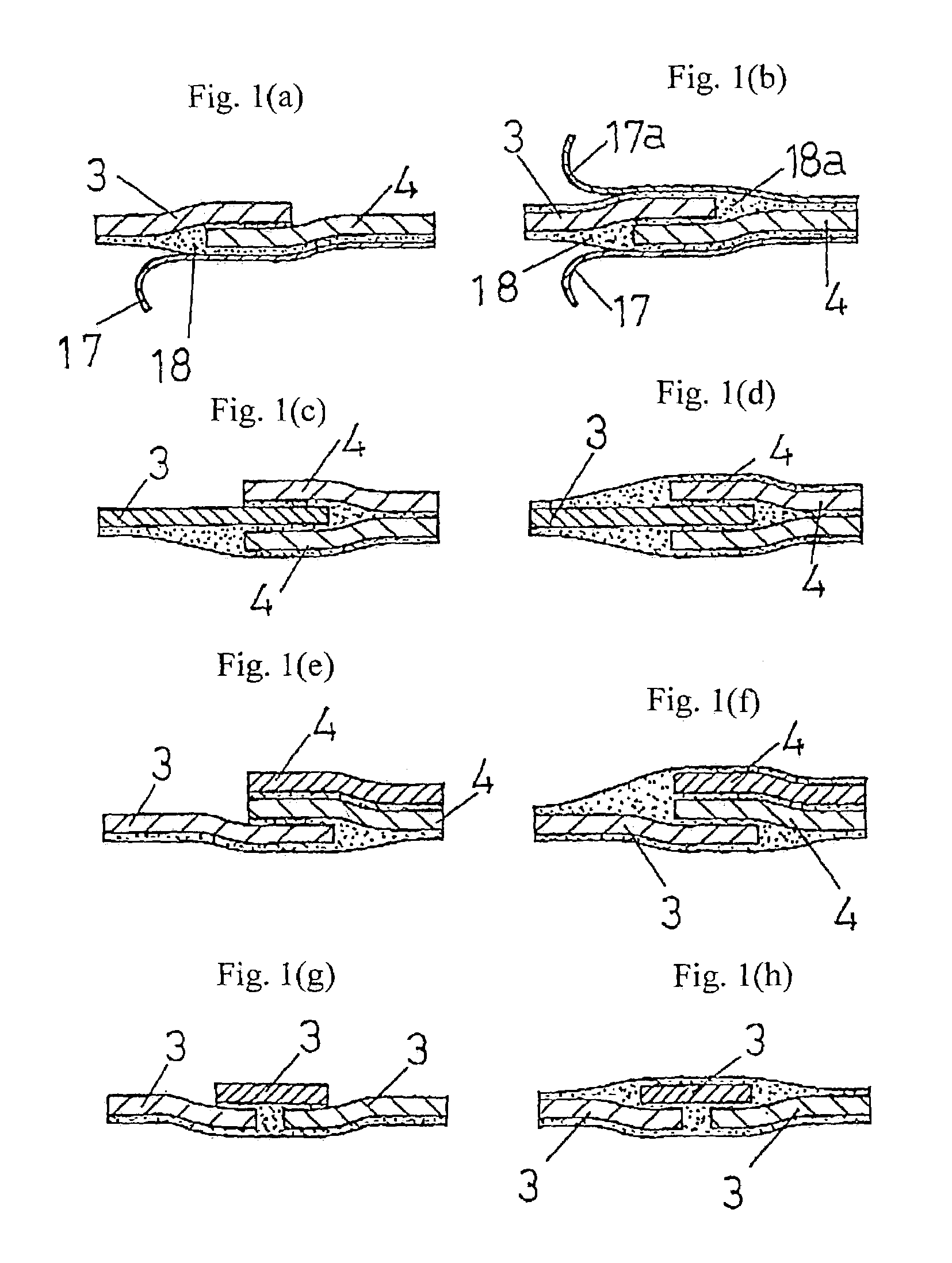
[0052]Embodiment 1 will be described referring to FIGS. 1(a)-(h).

[0053]This is an inventive method of joining screen materials (meshes or sheets) together.

[0054]The inventive method is favorable where different screens are joined together to have a more intricate screen structure.

[0055]For bonding, curing, and embossing of mesh or sheet screens, the method comprises steps of butt joining or overlap joining screens together, providing a peelable sheet or an embossed peelable sheet on upper, lower, or both sides of a bonded or cured joint and securing the joint with an adhesive agent or by thermal fusing or providing a set of molds for the joint and filling the molds with a molding agent, removing the peelable sheet or the embossed peelable sheet or the molds after the molding agent is cured, and smoothing the upper, and lower, or both sides of the bonded or cured joint, whereby a step at the joint between the screens is filled or the mesh is sealed with an adhesive agent and the scre...

embodiment 2

[0067]Embodiment 2 will now be described referring to FIGS. 2(a)-3(c).

[0068]The following is a technique for attaching a screen to a screen frame.

[0069]A method of spreading a screen printing screen comprises steps of: providing hooking portions in a screen frame, which is variable in each side length, for accepting screen hooking tools; hooking screen hooking tools of a screen into the hooking portions or joining the screen to the screen frame; and adjusting a length of each side of the screen frame with use of screen frame adjusting structure to provide tension on the screen suited for printing.

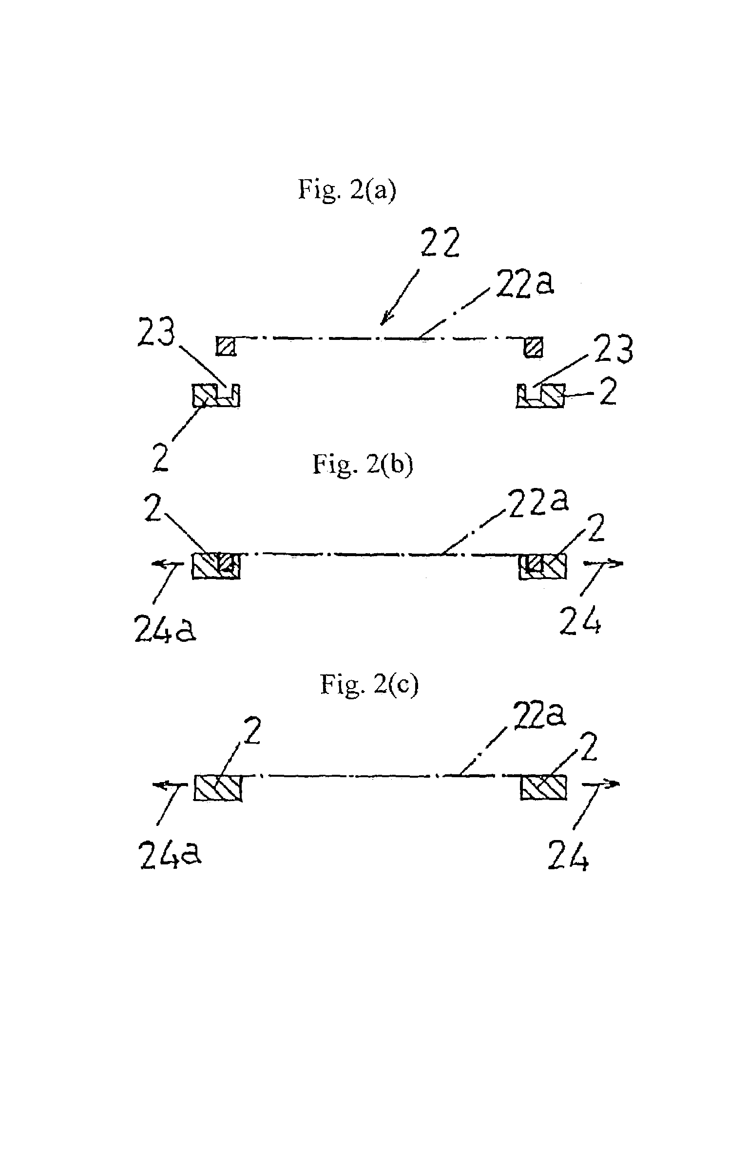
[0070]FIGS. 2(a)-2(c) illustrate a primary conception of a method of attaching a screen to a screen frame according to one embodiment of the present invention.

[0071]FIGS. 2(a) and 2(b) show a screen 22a held with its screen hooking tools 22 and spread by expanding two sides of a screen frame 2 in opposite directions 24 and 24a (outwardly of the screen frame).

[0072]Some examples of structure...

embodiment 3

[0107]Embodiment 3 will be described referring to FIGS. 6(a) and 6(b).

[0108]This relates to a screen frame employing a method of attaching a screen to a screen frame.

[0109]Hooking portions 23 for receiving screen hooking tools 22 are not illustrated and will be explained in no more detail.

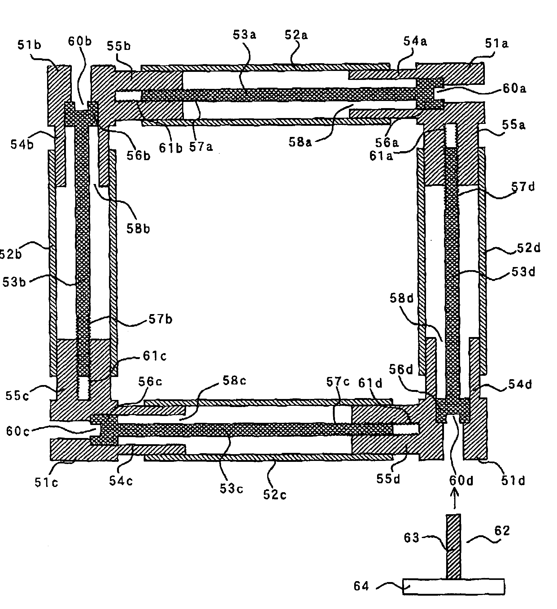
[0110]A screen printing screen frame which is variable in length of its frame sides, and to which a screen is attached with / without use of screen hooking tools fixed to the screen to spread the screen, is characterized by: the screen printing screen frame having each frame side thereof or each screen frame side intermediate portion thereof arranged for fitting loosely to each frame corner of the screen frame; the screen hooking tools fixed to the screen; fitting portions or joints of the screen fitting and hooking the screen hooking tools provided on an upper surface of each frame side for detachable connection, and screen frame side length extensible structure which consists mainly of male thread ...


PUM

PropertyMeasurementUnit
sizeaaaaaaaaaa
thicknessaaaaaaaaaa
thicknessaaaaaaaaaa

Abstract

The present invention relates to a screen for screen printing. More particularly, structure of the screen can have different types of mesh or sheets joined together. The present invention also relates to a method of detachably spreading a screen to a screen frame.

Description

[0001]This application is a continuation of International Application No. PCT / JP02 / 00241, with an international filing date of Jan. 16, 2002.TECHNICAL FIELD[0002]The present invention relates to a screen for screen printing. More particularly, it relates to a novel screen structure having different types of mesh or sheets joined together. Moreover, the present invention relates to a method of detachably spreading a screen to a screen frame, a screen frame used in the method, and a method of fabricating a planar mirror.BACKGROUND ART[0003]A conventional screen is proposed having a less expandable or mainly metal mesh provided as an image forming portion at a center thereof, and another mesh of a larger size provided about the image forming portion which is greater in terms of elasticity than the image forming portion (Japanese Utility Model Application Publication (JP-Y) No. 51-9297). More specifically, two types of mesh which are different in terms of expandability are joined togeth...

Claims


Application Information

Patent Timeline
Patent Type & Authority Patents(United States)
IPC IPC(8): B05C17/06B41F15/36B41M1/12
CPCB41M1/12B41F15/36
Inventor KASUYA, FURETSU
Owner KASUYA FURETABU
Why Eureka
Try Eureka