Method for automatic slip clutch tension on a reel

a technology of automatic slip clutch and reel, which is applied in the direction of sealing/packing, transportation and packaging, borehole/well accessories, etc., can solve the problems of destroying the umbilical or the reel, causing the damage of the umbilical, and destroying the umbilical with excessive tension, etc., to achieve the effect of constant tension limi

Active Publication Date: 2011-06-28
REEL POWER LICENSING
View PDF11 Cites 21 Cited by
  • Summary
  • Abstract
  • Description
  • Claims
  • Application Information

AI Technical Summary

Benefits of technology

[0011]A second object of the present invention is to provide a method of counting the revolutions of the spool during the umbilical deployment, determining the current radius to the cable being deployed, and automatically controlling the slipping torque in a fashion to maintain a constant tension limit on the umbilical.

Problems solved by technology

A danger to the umbilical or reel can occur in the event that the drilling riser or other pipe string to which the umbilical is attached is lowered while the reel spool is locked in position.
When this happens, an umbilical worth hundreds of thousands of dollars can be destroyed by the excessive tension and personnel can be injured.
Alternately, if the riser and umbilical are being deployed and the air pressure which runs the reel is lost, the failsafe brakes will automatically lock creating a chance that excessive tension will destroy the umbilical before the condition is recognized.

Method used


Image

  • Method for automatic slip clutch tension on a reel
  • Method for automatic slip clutch tension on a reel
  • Method for automatic slip clutch tension on a reel

Examples


Embodiment Construction

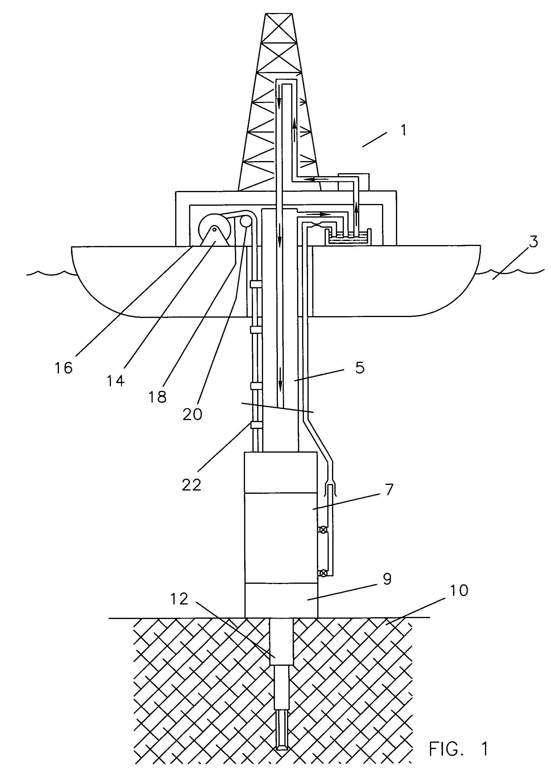
[0021]FIG. 1 shows a vessel 1 floating on the ocean 3 and having a drilling riser 5 extending down toward a blowout preventer stack 7. The blowout preventer stack 7 is landed on a subsea wellhead 9 which is in turn landed on the seafloor 10. Casing 12 extends into the seafloor below the subsea wellhead 9 for the purpose of drilling an oil or gas well.

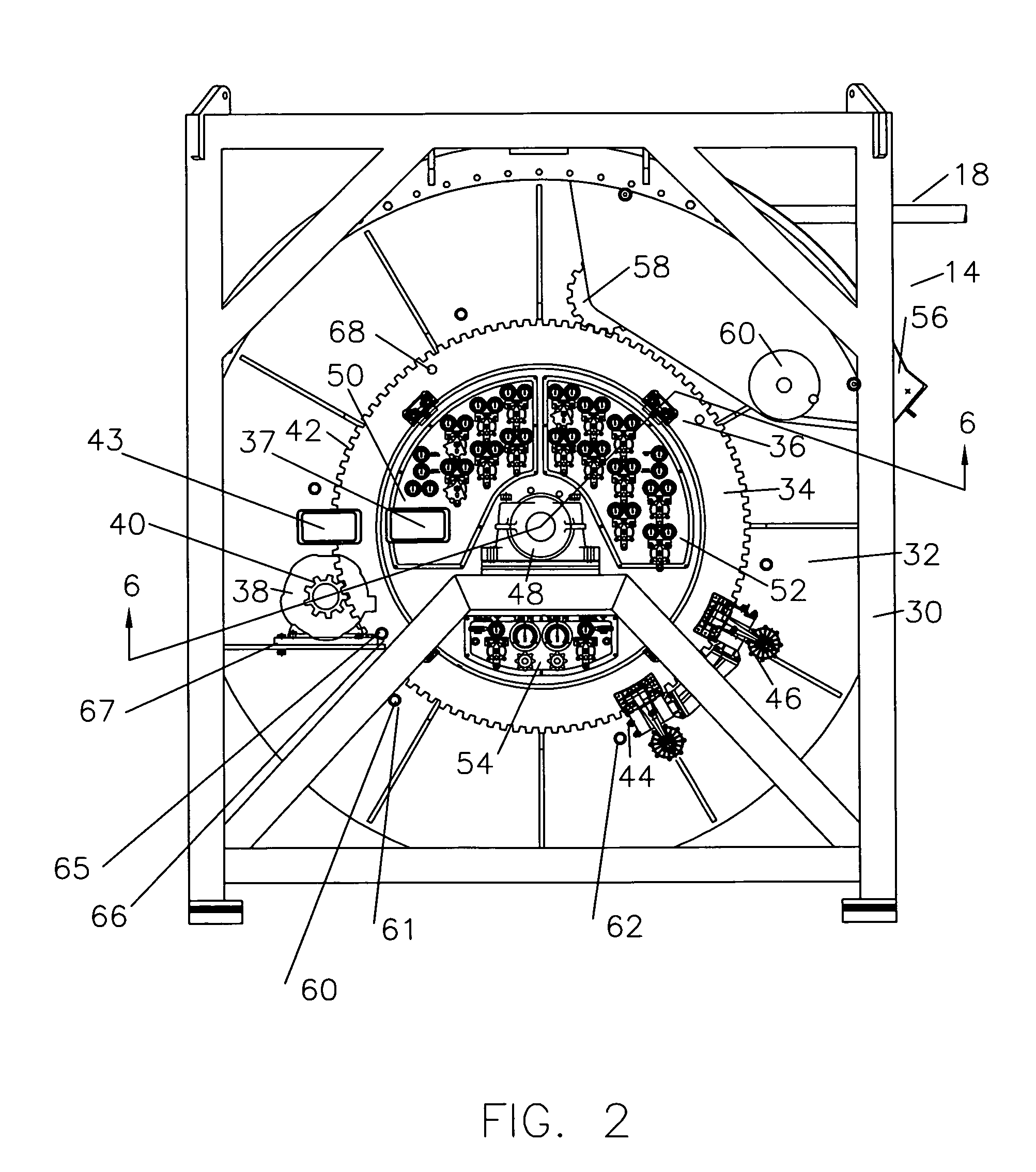
[0022]Reel 14 is positioned on the deck 16 of vessel 1 with umbilical 18 extending over pulley or sheave 20 and going down the side of the riser 5. Riser 5 is a series of jointed pipes and as they are sequentially connected and lowered into the ocean to lower the blowout preventer stack 7, clamps 22 secure the umbilical 18 to the drilling riser 5. The riser 5 and blowout preventer stack 7 may weigh as much as 650,000 lbs. When lowered with the umbilical 18 attached, if the rotation of the reel 14 is stopped, the full 650,000 lb. load can be put on the umbilical, destroying it. An even worse consequence is that the pulley or sheave 20 ca...


PUM


Abstract

The method of preventing over tension to an umbilical wrapped on the spool of an offshore reel when the umbilical is being normally deployed or retrieved or when the umbilical is unexpectedly pulled from the spool on the reel, comprising providing a main disk, mounting the main disk on the spool of the reel with a slip connection which will be automatically controlled, connecting motor power for the reel to the main disk, connecting brakes to the main disk, such that when the diameter of deployment varies the slip connection torque will be automatically adjusted and prevent the umbilical from being subjected to tension higher than the desired amount.

Description

CROSS-REFERENCE TO RELATED APPLICATIONS[0001]N / ASTATEMENT REGARDING FEDERALLY SPONSORED RESEARCH OR DEVELOPMENT[0002]N / AINCORPORATION-BY-REFERENCE OF MATERIAL SUBMITTED ON A COMPACT DISK[0003]N / ABACKGROUND OF THE INVENTION[0004]The field of this invention of that of umbilical reels which store and handle hose and / or electric and / or fiber optic control lines for deepwater offshore service. These reels typically pay out these lines, called umbilicals, and mechanics clamp the umbilical to a drilling riser or other pipe string being run to the seafloor. The actual weight of the umbilical is typically supported once it leaves the reel and in the water by the riser or pipe to which it is clamped. Typically these reel units have to be closely monitored to insure that excessive tension which can destroy the umbilical is not encountered as it is being deployed or in the event of unexpected movement of the riser or pipe to which it is clamped.[0005]When the drilling riser or other pipe string...

Claims


Application Information

Patent Timeline
Patent Type & Authority Patents(United States)
IPC IPC(8): B65H75/30B65H75/38B65H59/04
CPCE21B19/22B65H59/043
Inventor BAUGH, BENTON F.
Owner REEL POWER LICENSING
Why Eureka
Try Eureka