Mechanical heart valve prosthesis for the right ventricle

a heart valve and prosthesis technology, applied in the field of mechanical heart valve prosthesis, can solve the problems of thrombosis or emboli generation at local regions of stagnation, clots originating from valve hinge areas, and mechanical prosthetic heart valves have not been popular for implantation in the right ventricle, and achieve the effect of relatively high risk of thrombosis

Active Publication Date: 2018-01-18
UNIVERSITY OF GRONINGEN +1
View PDF1 Cites 2 Cited by
  • Summary
  • Abstract
  • Description
  • Claims
  • Application Information

AI Technical Summary

Benefits of technology

[0018]The leaflet passageways through the ear or, recess of each pivot member set allow flow through that ear and the associated cavity or through that recess when the leaflets are in the closed positions. Thus, a particularly effective flushing is concentrated in areas around the pivot axes of the leaflets, where the leaflets are suspended continuously and move relatively little as the leaflets move between open and closed positions, so the risk of formation of thrombosis would otherwise be relatively high. Moreover, this effect is of particular relevance at the low maximum pressure drops over a closed heart valve occurring in the right ventricle.

Problems solved by technology

Blood is a very delicate substance, and even minor abuses caused by turbulence and high shear stress can cause either thrombosis or emboli generation at local regions of stagnation.
This lower flow through the valve hinges is a probable cause for a higher incidence of clots originating from the valve hinge areas in mechanical heart valve prostheses in the right ventricle than in mechanical heart valve prostheses in the left ventricle.
For this reason, mechanical prosthetic heart valves have not been popular for implantation in the right ventricle.
However, the generally less thrombogenic alternatives of allograft (homograft) and biological heart valve prostheses have a much shorter lifetime than mechanical heart valve prostheses.
This disadvantage is often exacerbated when the heart valve prosthesis is applied as a right ventricle heart valve prosthesis, because many diseases resulting in a need of a right ventricular heart valve prosthesis are innate diseases, so that patients receiving a first right ventricular heart valve prosthesis, often have a life expectancy that is a multiple of the lifetime of an implanted allograft (homograft) or biological heart valve prosthesis and therefore can expect to require multiple heart valve replacements, each involving heart surgery or delivery via a catheter and each preceded by a period of relatively poor performance of the heart valve prosthesis approaching its end of lifetime.

Method used


Image

  • Mechanical heart valve prosthesis for the right ventricle
  • Mechanical heart valve prosthesis for the right ventricle
  • Mechanical heart valve prosthesis for the right ventricle

Examples


Embodiment Construction

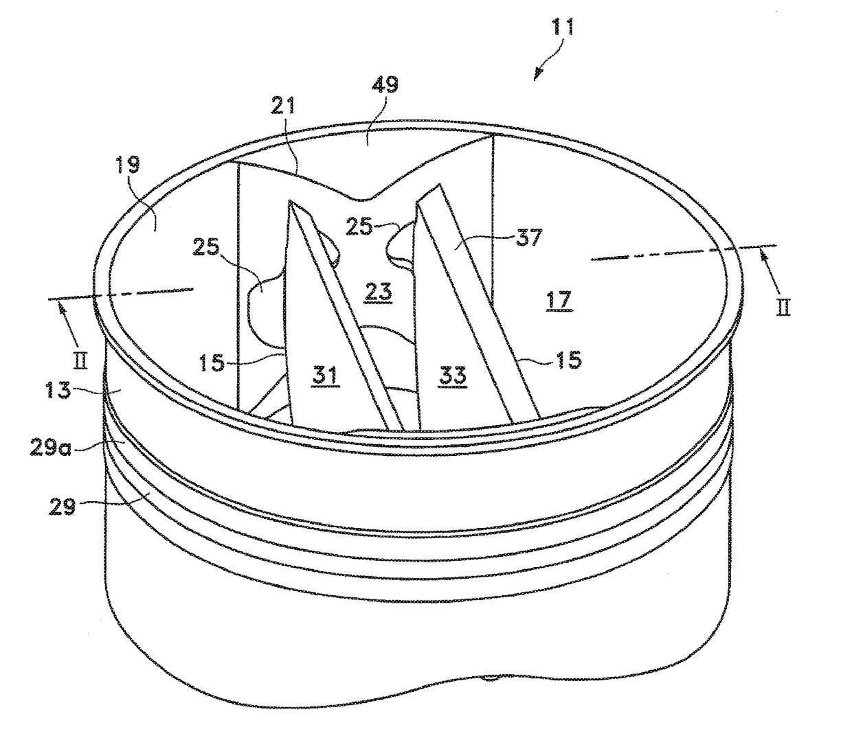
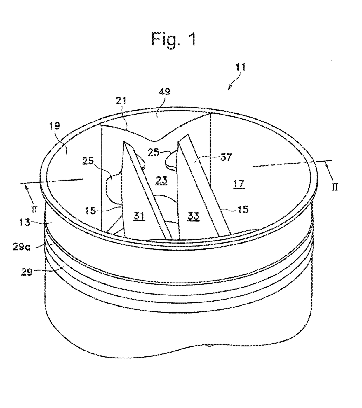
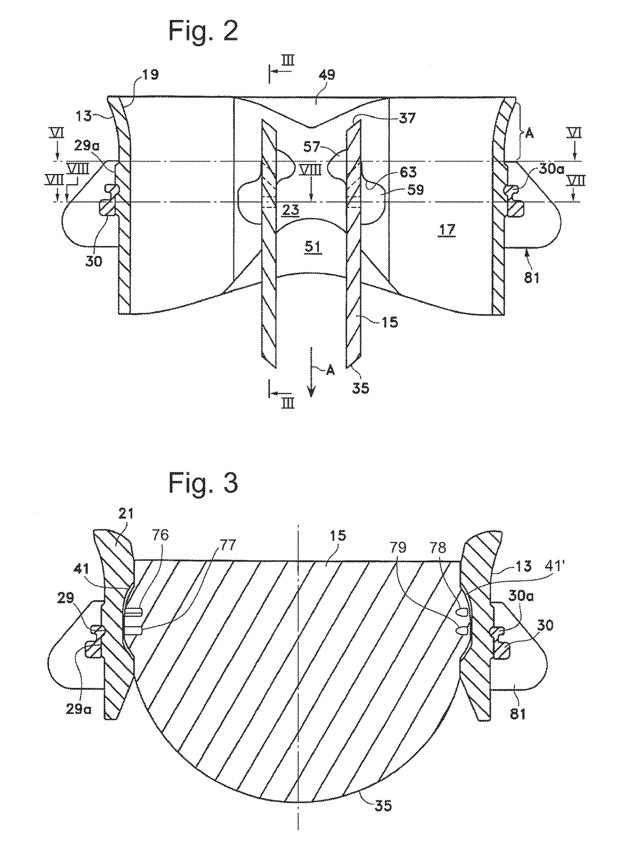
[0040]FIGS. 1-12 show an example of a prosthetic heart valve 11 according to the present invention and a variant thereon, both examples being of a basic design as disclosed in U.S. Pat. No. 5,641,324, but with modifications. Heart valve 11 includes a generally annular valve body 13 which carries a pair of pivoting occluders or leaflets 15 that alternately open and close either to allow, when in open positions (FIGS. 1-3 and the left half of FIG. 8), the smooth flow of blood in the downstream direction, as indicated by the arrow A in FIG. 2, or to prevent, when in the closed positions (FIGS. 4, 5, and 12 and the right half of FIG. 8) substantial backflow of blood, i.e. regurgitation. The valve body 13 defines a valve body passageway bounded by its generally arcuate, mostly cylindrical interior wall surface 17. The valve body 13 has a curved entrance region 19 at its upstream end, which has been found to substantially increase streamlined flow characteristics through the valve with lo...


PUM


Abstract

A prosthetic heart valve having a pair of cooperating leaflets mounted in a valve body to alternate between an open position where the flow of blood in a downstream direction is permitted and a closed position where the flow of blood in the reverse direction is counteracted. Pivot member sets at diametrically opposite sides of each leaflet guide the leaflets moving between the open and closed positions, each set including an ear or a recess cooperating with an associated cavity or knob of an interior surface of the valve body. Each ear or recess bounds at least one leaflet passageway through that ear or recess and located spaced from upstream and downstream ends of the ear for allowing flow through that ear and the associated cavity, or through that recess, when the leaflets are in the closed positions.

Description

FIELD AND BACKGROUND OF THE INVENTION[0001]The present invention relates to mechanical heart valve prostheses. Mechanical heart valve prostheses generally operate hemodynamically, in conjunction with the pumping action of the heart, to take the place of a defective natural valve. These valves have generally been designed to function with one or more occluders each swiveling to open and close a passageway through a generally annular valve body within which the occluders are suspended.[0002]Pyrolytic carbon has been determined to be adequately non thrombogenic for use as a heart valve material. The problem of combatting thrombosis in mechanical valves is presently felt to lie in preventing excess turbulence, high shear stresses and local regions of stasis. Blood is a very delicate substance, and even minor abuses caused by turbulence and high shear stress can cause either thrombosis or emboli generation at local regions of stagnation. Regions of the valve that are particularly suscept...

Claims


Application Information

Patent Timeline
Patent Type & Authority Applications(United States)
IPC IPC(8): A61F2/24F16K15/03
CPCA61F2/2403A61F2/2409A61F2220/0091F16K15/036
Inventor EBELS, TJARKPRAGT, HANNA
Owner UNIVERSITY OF GRONINGEN
Why Eureka
Try Eureka