
Central nervous system cooling catheter

a cooling catheter and central nervous system technology, applied in the field of central nervous system cooling catheters, can solve the problems of high risk of blood occlusion and infection of catheters placed in the brain or ventricles, and achieve the effect of reducing the risk of infection and reducing the risk of catheter occlusion

Active Publication Date: 2007-01-04
KHANNA ROHIT
View PDF40 Cites 56 Cited by
  • Summary
  • Abstract
  • Description
  • Claims
  • Application Information

AI Technical Summary

Benefits of technology

[0010] For selective brain cooling, in one embodiment of the present invention, a flexible catheter is inserted into the cerebral lateral ventricle to cool the cerebrospinal fluid and henceforth brain. The catheter has three lumens with a distal heat conductive element which also has holes to allow for drainage of cerebrospinal fluid. Two lumens are connected at the tip of the catheter and allow for circulation of a coolant. The third lumen has holes at the distal end that allows for drainage of cerebrospinal fluid as well as intracranial pressure monitoring similar to a ventriculostomy. In another embodiment of this catheter, ultrasonic or laser energy is delivered either through the catheter wall or lumen. Catheters placed in the brain or ventricles carry a high risk of occlusion from blood as well as infection. Ultrasonic or laser energy provides clot lyses and maintains catheter patency. Impregnation of the catheter wall with anticoagulant / antithrombotic and antimicrobial agents which are slowly released also reduces the risk of catheter obstruction and infection.
[0013] The catheters are designed to allow an inert coolant to circulate in the lumens without direct exposure to the brain or spinal cord and thereby altering the brain or spinal cord temperature. This allows for selective cooling of the brain and spinal cord for treatment of injury from trauma, ischemia, hypoxia and / or cerebral swelling.

Problems solved by technology

Catheters placed in the brain or ventricles carry a high risk of occlusion from blood as well as infection.

Method used


Image

  • Central nervous system cooling catheter
  • Central nervous system cooling catheter
  • Central nervous system cooling catheter

Examples


Embodiment Construction

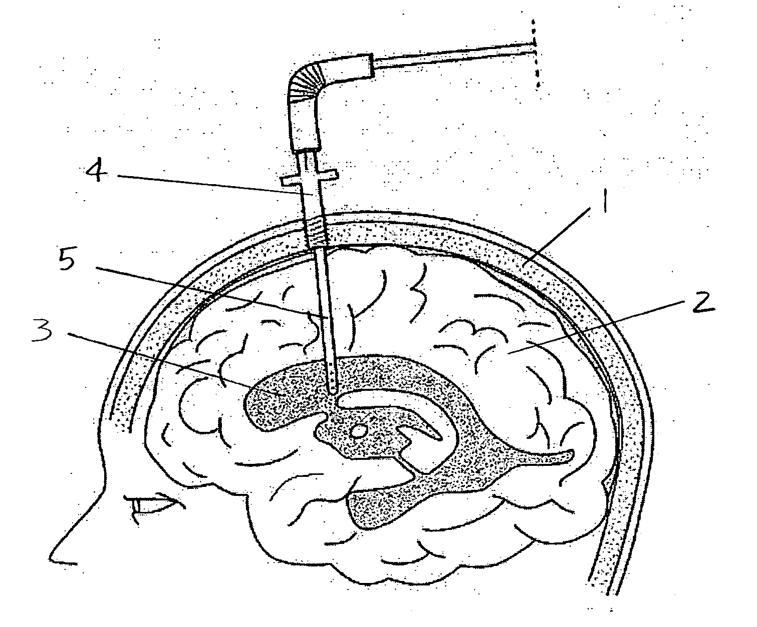
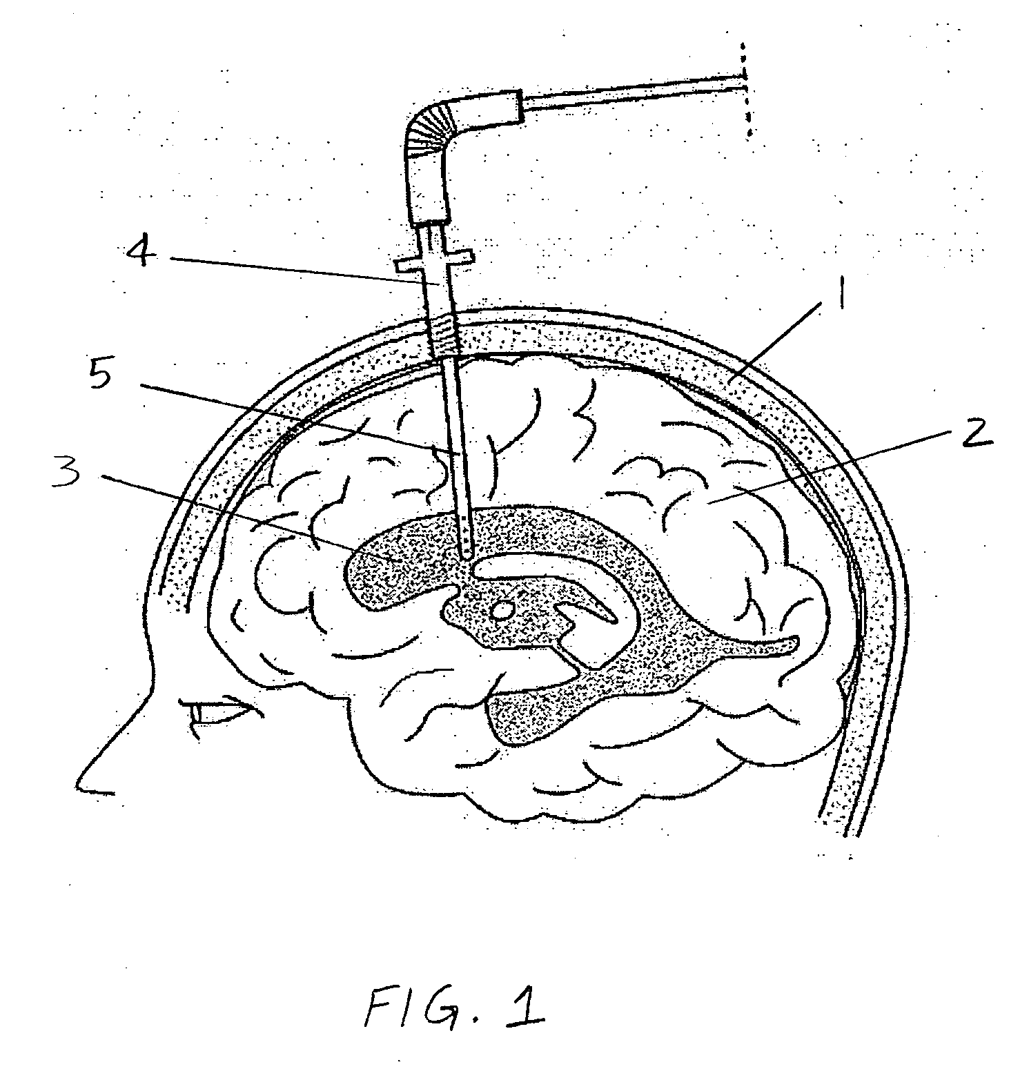
[0078] In one method of selective brain and / or spinal cooling, a catheter as shown in FIG. 1, can be placed into the ventricle of the brain or the subdural space of the spine. This allows for cooling of the cerebrospinal fluid and hence the brain and / or spinal cord selectively. These catheters can be placed in the lateral ventricles using the standard landmarks or can be precisely placed with stereotactic guidance or use of an endoscope. The bolt 4 secures the catheter 5 to the skull 1. The catheter 5 is placed into the cerebrospinal fluid in the ventricle 3.

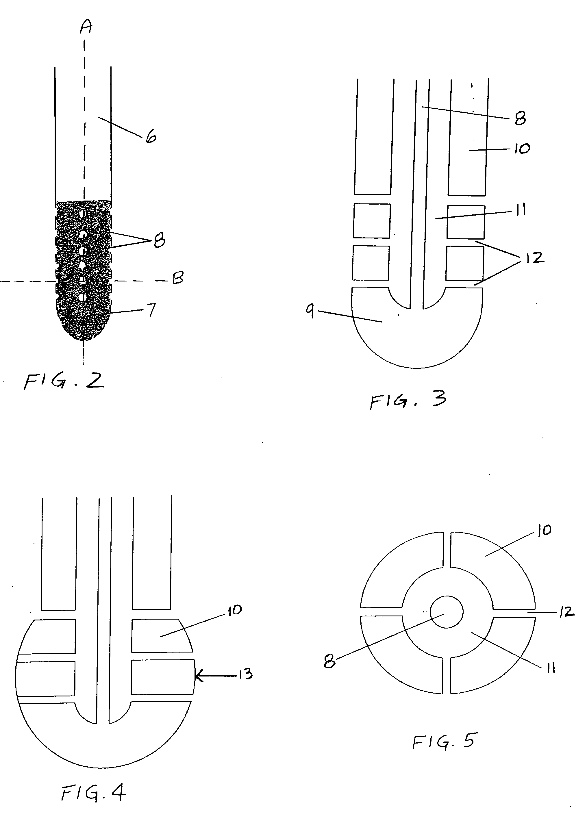
[0079] As illustrated in FIG. 2, the catheter has a proximal portion 6 and a distal heat transfer element 7. The distal heat transfer element 7 has several circumferential holes 8 that allow drainage of cerebrospinal fluid as well as monitoring of intracranial pressure.

[0080] In one embodiment of the cooling catheter as shown in FIGS. 3-5, the heat exchange fluid or compressed refrigerant enters through the central lumen 8 int...


PUM


Abstract

The invention provides a method and apparatus for performing selective hypothermia to the brain and spinal cord for injury protection without the need for systemic cooling. A flexible catheter is inserted into the cerebral lateral ventricle or spinal subdural space. The catheter has lumens with a heat transfer element. The lumens of the catheter circulate a coolant and communicate at the distal heat transfer element for transfer of heat from the cerebrospinal fluid. Furthermore a method of maintaining catheter patency and providing blood clot hemolysis and drainage is also provided through the use of ultrasonic and / or laser energy delivered through the catheter.

Description

[0001] This application is a continuation of U.S. application Ser. No. 10 / 136,003 filed Dec. 20, 2002, titled “Selective brain and spinal cord hypothermia method and apparatus,” now U.S. Pat. No. 6,699,269. BACKGROUND OF THE INVENTION [0002] The current invention relates to regulation of the temperature in the brain and spinal cord. The invention describes a method and apparatus for altering the temperature of the brain surface and / or the cerebrospinal fluid in the ventricles of the brain and surrounding the spinal cord. [0003] Hypothermia has been shown to provide cerebral and spinal cord injury protection from either trauma, ischemia, or hypoxia. Ischemia may occur from cardiac arrest, cardiac failure, stroke, head or spinal cord injury, aneurysm surgery, cardiac surgery, and aortic or carotid surgery. Hypothermia is also effective in reducing increased intracranial pressure from cerebral swelling. The mechanisms involved in hypothermic cerebral protection are several-fold and inc...

Claims


Application Information

Patent Timeline
IPC IPC(8): A61F7/00A61F7/12
CPCA61F7/12A61F2007/126A61F2007/0056A61F7/123
Inventor KHANNA, ROHIT
Owner KHANNA ROHIT
Learn More