Method for upgrading a dial indicator to provide remote indication capability

a dial indicator and remote indication technology, applied in the field of dial indicators, can solve the problems of not being economically feasible to replace the existing gauge, unable to provide local visual and remote indication, and the above system is complex and therefore may be relatively expensiv

Inactive Publication Date: 2004-06-01
INVENSYS SYST INC
View PDF22 Cites 27 Cited by
  • Summary
  • Abstract
  • Description
  • Claims
  • Application Information

AI Technical Summary

Problems solved by technology

The above systems tend to be complex and therefore may be relatively expensive.
Further, for some applications for which both local and remote indication are desirable, it may not be economically feasible to replace the existing gauge.
Further still, for many applications, dial indicators providing for both local visual and remote indication may not be commercially available.

Method used


Image

  • Method for upgrading a dial indicator to provide remote indication capability
  • Method for upgrading a dial indicator to provide remote indication capability
  • Method for upgrading a dial indicator to provide remote indication capability

Examples


Embodiment Construction

.

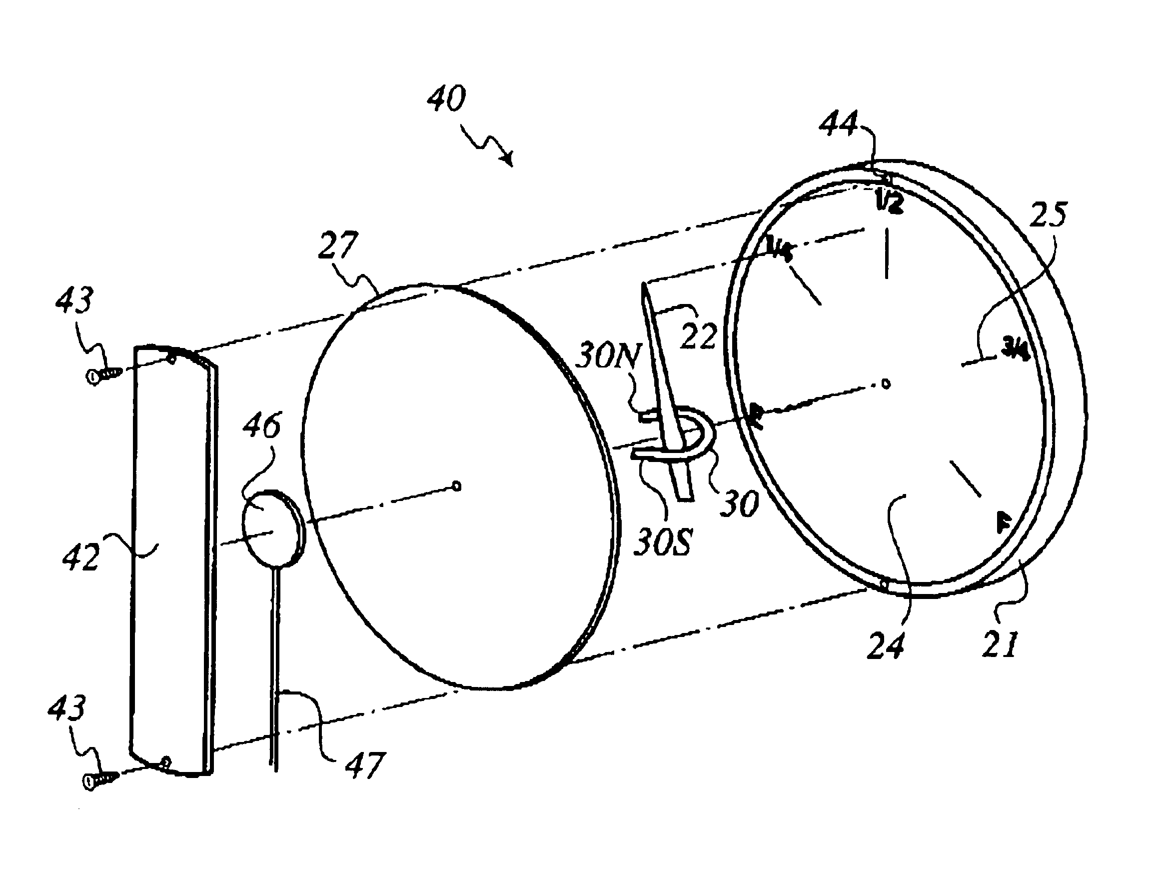
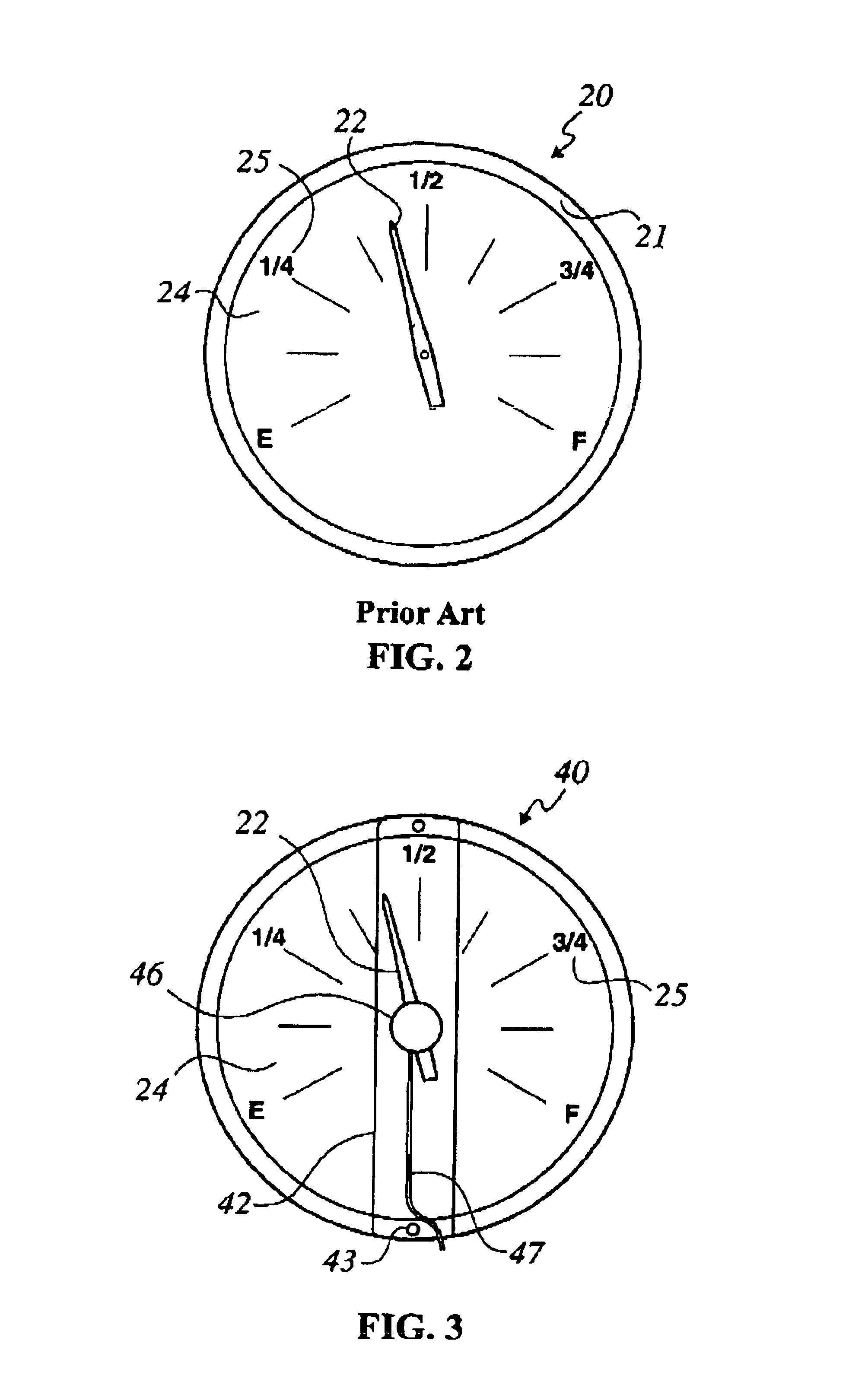
Referring now to FIG. 2, a conventional dial indicator 20 typically includes a housing 21 having a faceplate 24 with indicia 25 printed thereon. A rotary dial pointer 22 coupled to a conventional sensor mechanism (not shown) provides for a visible indication of the measured physical parameter. Dial indicator 20 also typically includes a transparent cover 27 (see FIGS. 4-5) on the front face thereof.

Referring again to FIGS. 3-5, embodiments of a dial indicator 40 including the present invention are illustrated and described in more detail. Referring initially to FIG. 3, dial indicator 40 is similar to dial indicator 20 in that it includes a housing 21 having a faceplate 24 with indicia 25 printed thereon and a rotary pointer 22 for providing a visible indication of the measured physical parameter. Rotary pointer 22 may be any type that is typically used in gauges known in the art, such as shown and described in U.S. Pat. No. 4,975,687 to Murphy, Jr. et al. Dial indicator 40 further ...


PUM

PropertyMeasurementUnit
physical parameteraaaaaaaaaa
electrical outputaaaaaaaaaa
liquid levelaaaaaaaaaa

Abstract

A dial indicator, method, and kit for upgrading a dial indicator to provide both local visible and remote indication of a measured physical parameter is provided. A magnetic rotary pointer is provided by coupling a magnet to a pointer, or by providing a replacement pointer having an integral magnet, so that the magnetic rotary pointer is rotatable in response to a change a measured physical parameter. A potentiometer is magnetically coupled to the magnetic rotary pointer, and is fastened to a front side of the dial indicator.

Description

(1) Field of the InventionThe present invention relates generally to a dial indicator, and more particularly relates to a dial indicator capable of providing both local visible indication and remote indication of a physical parameter.(2) Background InformationDial indicators (also variously referred to as dial gauges, indicator gauges, dial faces, and / or analog gauges) are commonly used to indicate a host of physical parameters such as temperature, pressure, electrical properties, liquid levels, among others. For example, liquid storage tanks for fuel, oil, propane, natural gas, and ammonia typically include a dial indicator attached thereto for providing an on-site, visible reading of the liquid level (i.e., the percentage of the total tank volume occupied by the liquid. For many applications it is desirable, both for convenience and economic factors, to have both local visible indication and remote indication of the above-mentioned physical parameters. For example, it is generally...

Claims


Application Information

Patent Timeline
Patent Type & Authority Patents(United States)
IPC IPC(8): G01D13/00G01D13/26
CPCG01D13/26
Inventor SCHENK, JR., WILLIAM P.
Owner INVENSYS SYST INC
Why Eureka
Try Eureka