
Plasma display apparatus

a technology of display apparatus and plasma, which is applied in the direction of television system, identification means, instruments, etc., can solve the problems of reducing the productivity of the apparatus, increasing the total weight of the display apparatus, and difficult to perform an assembly operation to form the chassis structur

Inactive Publication Date: 2004-06-01
PANASONIC CORP +1
View PDF2 Cites 69 Cited by
  • Summary
  • Abstract
  • Description
  • Claims
  • Application Information

AI Technical Summary

Benefits of technology

"The present invention relates to an improved plasma display apparatus with a chassis structure that supports a plasma display panel and a circuit board mounting a drive circuit for driving the plasma display panel. The chassis structure includes a first chassis member and a second chassis member with a plurality of support portions provided between the two chassis members for supporting the two chassis members and forming a predetermined interval between the two chassis members. The second chassis member is fixed on the backside of the plasma display panel. The technical effects of the present invention include a sufficient support strength and a sufficient heat radiation effect, as well as an improved production cost and efficiency."

Problems solved by technology

This, however, undesirably increases the total weight of the plasma display apparatus.
Moreover, since the chassis structure involves a lattice arrangement, it will be difficult to perform an assembling operation to form the chassis structure, because the longitudinal and lateral members 3A and 3B having an increased thickness and an increased weight are relatively difficult to deal with.
As a result, there has been a problem that the productivity is comparatively low.
In addition, as to the heat radiation of the conventional plasma display apparatus, since the lateral members 3B are arranged at an interval on the PDP 1, it is difficult for the whole apparatus to obtain a uniform radiation effect, thus making it impossible to ensure a sufficient each radiation.
However, if the chassis structure is required to ensure an increased strength, the same measure would have to be taken in the same manner as described in the above, bringing about the same problems of increasing the total weight of the display apparatus as well as increasing the production cost.

Method used


Image

  • Plasma display apparatus
  • Plasma display apparatus
  • Plasma display apparatus

Examples


first embodiment

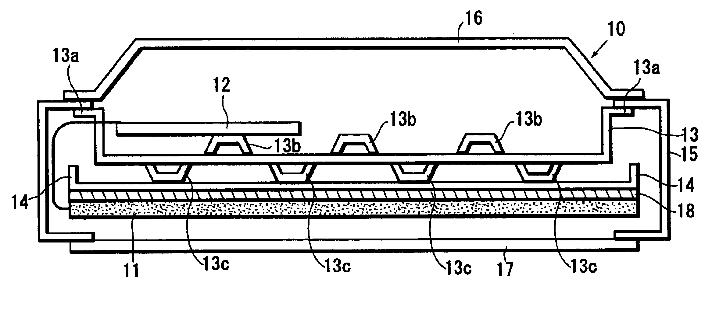
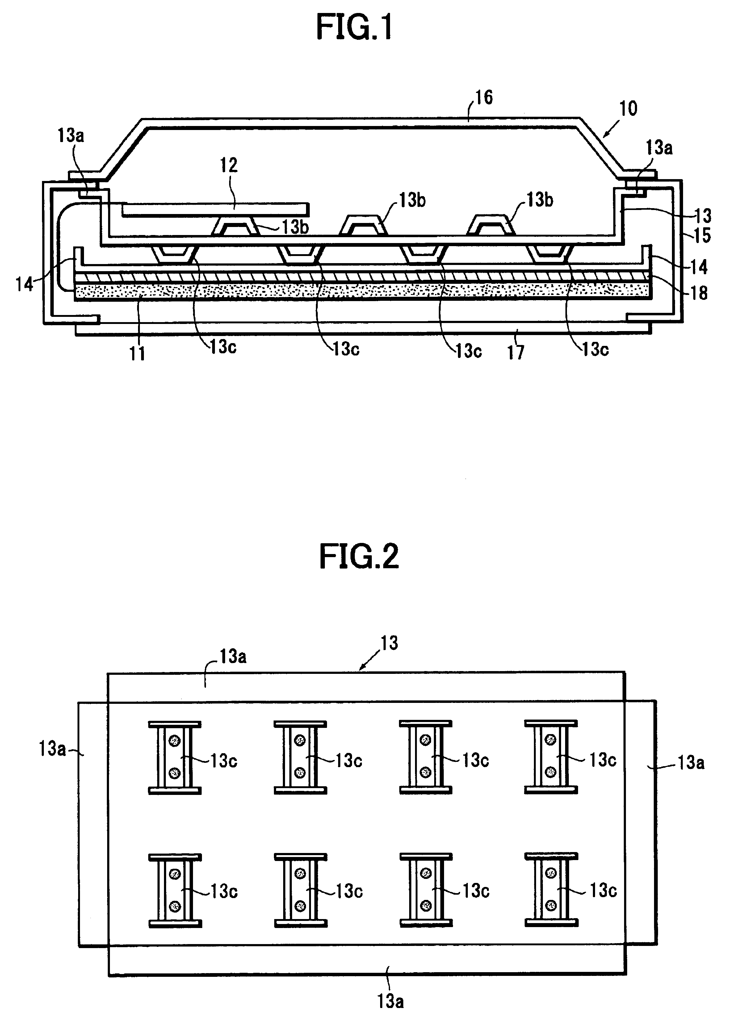
A first embodiment of the present invention will be described in the following with reference to the accompanying drawings. FIG. 1 is an explanatory view showing the internal structure of a plasma display apparatus formed according to the present invention. As shown in FIG. 1, a plasma display apparatus 10 comprises a plasma display panel (PDP) 1 formed by bonding together two glass substrates (with one serving as a front substrate and the other a rear substrate) with a narrow discharge space formed therebetween, a circuit board mounting a power source circuit and a drive circuit for driving the PDP 11, a first chassis member 13 and a second chassis member 14 for supporting the PDP 11 and the circuit board 12. Specifically, the PDP 11 and the chassis members 13, 14 are enclosed in a housing formed by a pair of side panels 15, a rear case 16 and a front panel 17.

The first chassis member 13 is a plate-like member made of a metal such as aluminum. Two side panels 15 are connected to tw...

second embodiment

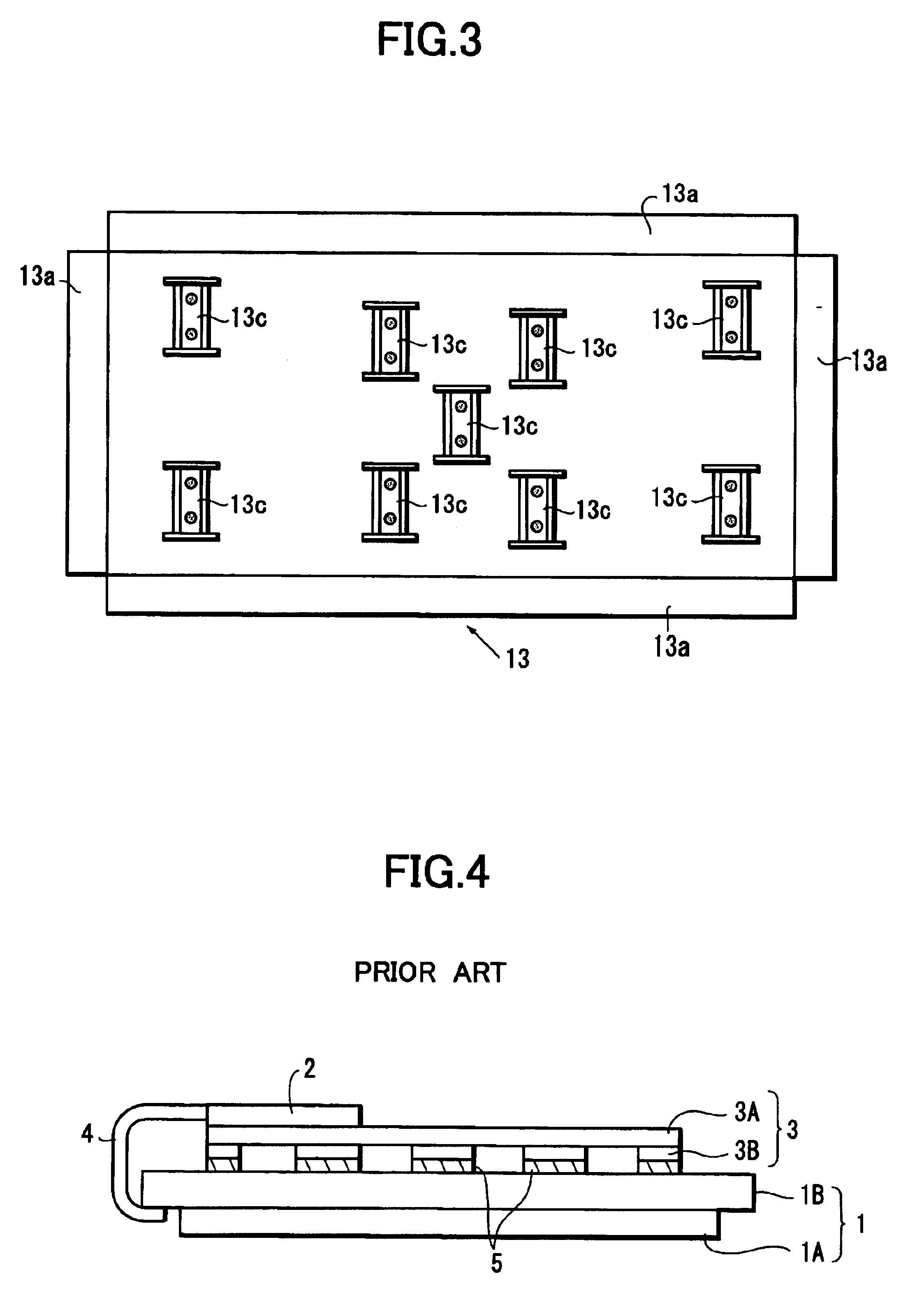
the present invention will be described with reference to FIG. 3 which is also a plan view showing the first chassis member 13 when viewed from the second chassis member 14. In fact, the second embodiment is almost the same as the first embodiment shown in FIG. 2 except that the projections 13 provided on the central area of the first chassis member 13 are more than those provided close to the edge areas thereof. In this way, although the central area of the plasma display panel produces an amount of heat larger than any other areas, this amount of heat can be efficiently transferred outwardly by way of the centrally located projections 13c, thereby ensuring a uniform temperature distribution on the PDP 11, and thus obtaining a further improved heat radiation effect.

As described in the above, each of the chassis structures described in the above embodiments includes two pieces of metal plates, so that it becomes possible to manufacture an improved plasma display apparatus high in ra...


PUM


Abstract

A plasma display apparatus includes a plasma display panel, a circuit board mounting a drive circuit for driving the plasma display panel, a chassis structure provided on the backside of the plasma display panel for supporting the plasma display panel and for mounting the circuit board. In particular, the chassis structure comprises a first chassis member mounting the circuit board, and a second chassis member fixed on the backside of the plasma display panel, a plurality of support portions provided between the first and second chassis members for supporting the two chassis members and for forming a predetermined interval between the two chassis members.

Description

1. Field of the InventionThe present invention relates to a plasma display apparatus, particularly to a plasma display apparatus having an improved chassis structure provided on the backside of a plasma display panel.2. Description of the Related Prior ArtRecently, plasma display apparatus has been in spreading which is usually large in screen size and thin in thickness. Such a plasma display apparatus comprises a plasma display panel (hereinafter, simply referred to as PDP) including a pair of substrate plates arranged to face each other with an electric discharge space formed therebetween, a plurality of row electrodes and a plurality of column electrodes arranged orthogonal to the row electrodes, a plurality of electric discharge cells each formed at an intersection between a row electrode and a column electrode, so that a desired displaying can be achieved by effecting electric discharges in various discharge cells.Further, such a plasma display apparatus has a chassis structure...

Claims


Application Information

Patent Timeline
Patent Type & Authority Patents(United States)
IPC IPC(8): H01J17/49G09F9/00H04N5/64H05K7/20
CPCH05K7/20963
Inventor OISHI, TOSHIHARUYOKOI, SADAOKANEKO, KOICHITAKAO, DAISUKE
Owner PANASONIC CORP
Learn More