Weight plate

a weight plate and plate body technology, applied in the field of weight plates, can solve the problems of difficult lifting maneuver, flat sided weight plates do not have a convenient hand hold for users, and the difficulty of picking up weight plates

Inactive Publication Date: 2004-06-08
USA SPORTS
View PDF53 Cites 73 Cited by
  • Summary
  • Abstract
  • Description
  • Claims
  • Application Information

AI Technical Summary

Problems solved by technology

One major problem with free weight lifting and a cause of many accidental injuries is that it is difficult to pick up a weight plate, particularly disc-shaped plates having flat sides.
The problem, simply stated, is that a flat sided weight plate does not have a convenient hand hold to be grasped by the user for lifting it off a flat surface, such as a floor or a stack of weight plates.
Of course, the heavier the weight plate, the more difficult the lifting maneuver becomes.
Lifting a weight plate employing the generally accepted method described above can cause injury by slipping out of the grasp of the user and falling on toes or finger tips.
The same problem is encountered, however, when an individual attempts to lift the weight by the circumferential flange.
The typical weight plate is not only difficult to lift off a flat surface as noted above, but also difficult to hold and raise it up, perhaps to chest level, to mount the weight plate on an exercise apparatus.
Likewise, removing a weight plate from a relatively high position on an exercise apparatus is also difficult and if not done with care may result in injury to the individual removing the weight plate.
Another problem associated with weight plates having a circumferential upstanding flange on one or both sides of the weight plate, is that the weight plates mounted on the weight bar are not in facing contact.

Method used


Image

  • Weight plate
  • Weight plate
  • Weight plate

Examples


Embodiment Construction

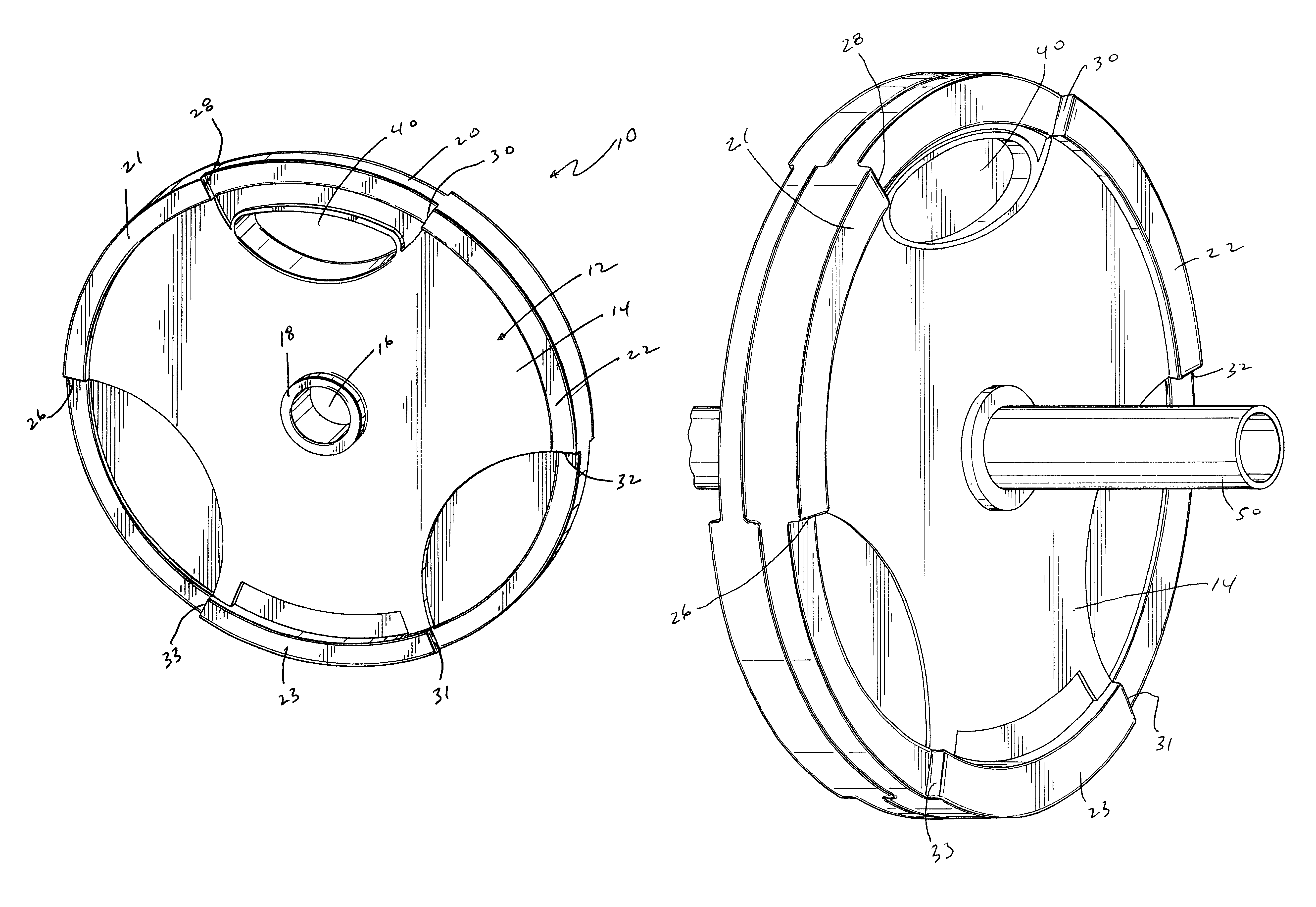
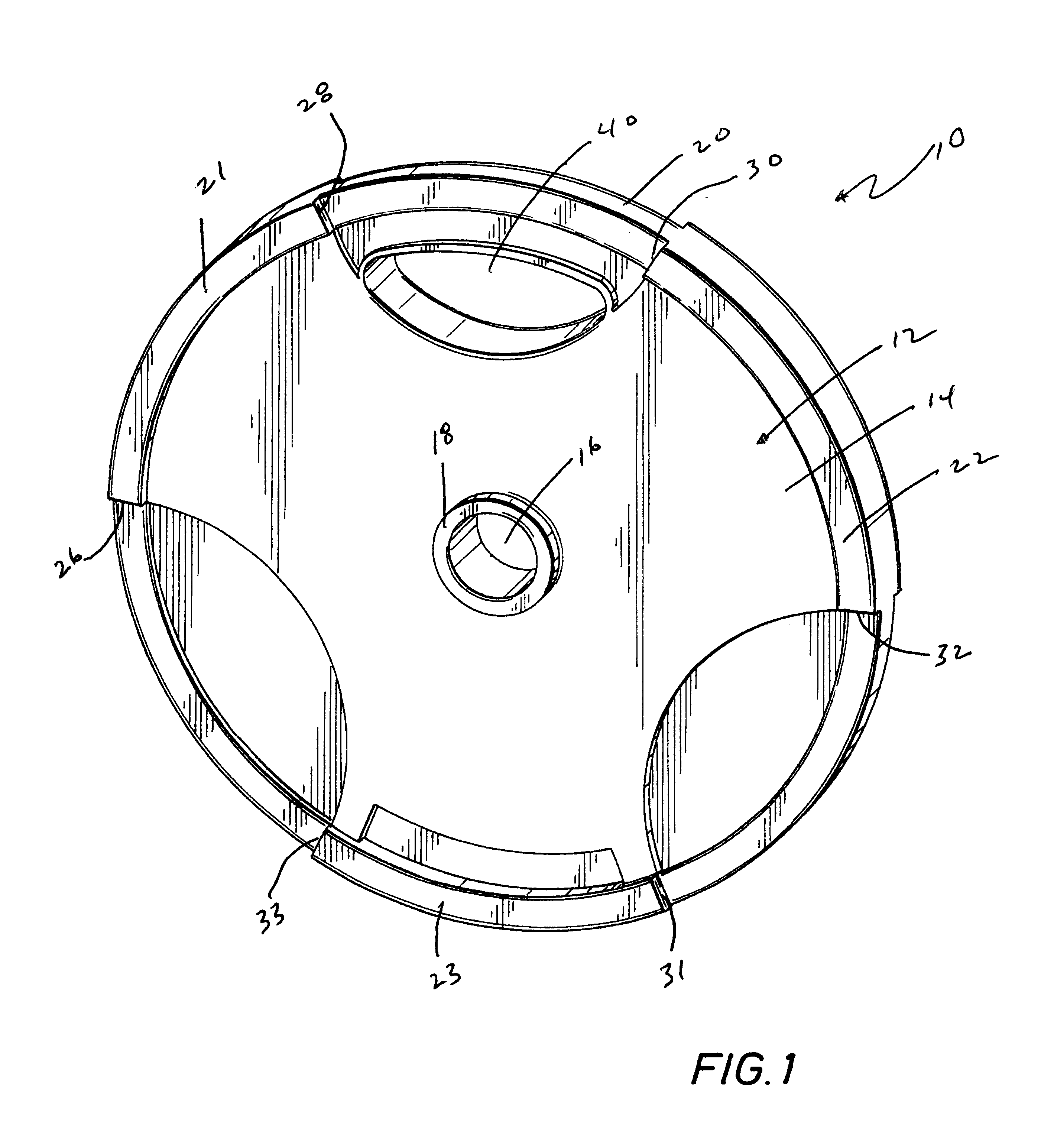
Referring first to FIG. 1, the weight plate of the invention is generally identified by the reference numeral 10. The weight plate 10 may be cast, rubber coated and / or polyurethane coated. The weight plate 10 includes a substantially flat body 12 defined by first and second planar surfaces 14. The planar surfaces 14 are generally opposed and define the thickness of the plate 10. A centrally located bore 16 defines the rotational axis of the plate 10 and is adapted to receive a mounting member, such as a barbell or weight bar. The bore 16 is further defined by integrally formed collars 18 which circumscribe the bore 16 and project outwardly from the surfaces 14 of the weight plate body 12. The collars 18 are oriented perpendicular to the body surfaces 14 and add axial length to the bore 16. It is understood that the diameter of the bore 16 may vary to accommodate the diameter of a barbell or dumbbell bar to be received through the bore 16. The diameter of the bore 16 will generally v...


PUM


Abstract

An improved weight plate includes a planar body having a central opening for receiving a barbell or dumbbell bar therethrough. The weight plate includes oppositely facing flange members extending partially about the perimeter of the weight plate. The opposed ends of the flange members are spaced from each other and define a gap therebetween. The flange members extend perpendicularly from both sides of the weight plate planar body about the perimeter thereof. The weight plate includes at least one opening formed adjacent the perimeter of the weight plate. The opening is adapted to receive one or more fingers of an average human hand for securely grasping and lifting the weight plate. Adjacent weight plates mounted on a barbell bar are adapted for interlocking engagement.

Description

BACKGROUND OF THE DISCLOSUREThe present invention relates generally to physical fitness equipment, particularly to weight plates which may be used during weight lifting.The physical fitness industry has seen tremendous growth during the past couple of decades. A wide array of exercise apparatus is available to meet the needs of a growing population of consumers engaged in physical fitness activities. Some of the new exercise apparatus include high tech interactive features which can display sophisticated graphics and information for engaging and holding the attention of the user while he exercises. Little has changed however in the area of free weight exercises.Free weight exercises generally require weight plates for use with barbells and dumbbells. The weight plates are typically disc-shaped and include a center opening for receiving a barbell or dumbbell bar through the opening. Generally, a retention collar mounted onto the barbell or dumbbell bar retains the weight plate on the...

Claims


Application Information

Patent Timeline
Patent Type & Authority Patents(United States)
IPC IPC(8): A63B21/072A63B21/06
CPCA63B21/06A63B21/072A63B21/0728A63B21/075A63B21/0724A63B2071/0063
Inventor LIEN, LOUISWU, ANNIETANKO, ROBERTSEGOVIA, EUGENEBYRD, RICKHARMS, ROBERT E.
Owner USA SPORTS
Why Eureka
Try Eureka