
Method and apparatus for reducing power consumption

a technology of power consumption and power consumption, applied in the direction of instruments, liquid/fluent solid measurement, generating/distributing signals, etc., can solve the problems of increasing power consumption, reducing power consumption, and reducing power consumption

Inactive Publication Date: 2004-06-08
ORACLE INT CORP
View PDF14 Cites 232 Cited by
  • Summary
  • Abstract
  • Description
  • Claims
  • Application Information

AI Technical Summary

Benefits of technology

"The present invention relates to a method and apparatus for transitioning between low-power modes of operation in electronic devices such as computer systems. The invention addresses the problem of reducing power consumption in electronic devices while still ensuring proper operation and avoiding delays caused by long power-down periods. The invention uses a phased lock loop (PLL) controller to synchronize clock signals and reduce power consumption during low-power modes of operation. The invention also includes a method for controlling thermal cycles in the computer system to prevent system failure or malfunctions. The invention can be used in computer systems and other electronic devices to reduce power consumption and improve their overall performance."

Problems solved by technology

For a variety of reasons, power consumption has become an increasingly significant issue for electronic devices such as computer systems.
Additionally, power consumption is related to the amount of heat produced by the electronic device.
Additionally, reduced heat dissipation generally means that electronic components may be more densely packed, leading to smaller, more compact packages.
For example, many computer systems employ a monitor, which consumes substantial power.
Thus, during low-power mode, the system may turn the monitor off.
However, when a user attempts to operate a computer system that has its peripheral devices powered-down, a significant delay occurs before the computer system can restore power to the peripherals and begin responding to the requests of the user.
Thus, where the clock frequency is changed dramatically, such as by half or more, the PLLs may operate marginally or erratically.
Faulty operation of the PLLs may produce unstable operation of the computer system as a whole, causing the system to crash or lock-up.
Thus, during transitions from normal to low-power mode, or vice versa, the system may fail, again encouraging the user to disable the power saving feature.

Method used


Image

  • Method and apparatus for reducing power consumption
  • Method and apparatus for reducing power consumption
  • Method and apparatus for reducing power consumption

Examples


Embodiment Construction

Illustrative embodiments of the invention are described below. In the interest of clarity, not all features of an actual implementation are described in this specification. It will of course be appreciated that in the development of any such actual embodiment, numerous implementation-specific decisions must be made to achieve the developers' specific goals, such as compliance with system-related and business-related constraints, which will vary from one implementation to another. Moreover, it will be appreciated that such a development effort might be complex and time-consuming, but would nevertheless be a routine undertaking for those of ordinary skill in the art having the benefit of this disclosure.

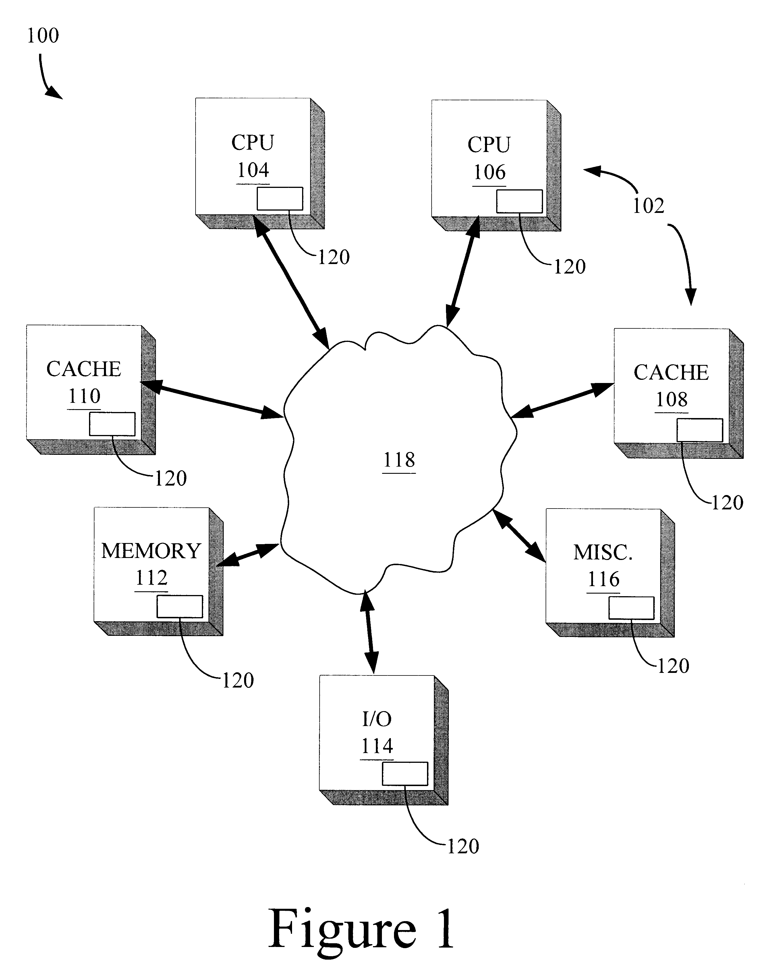
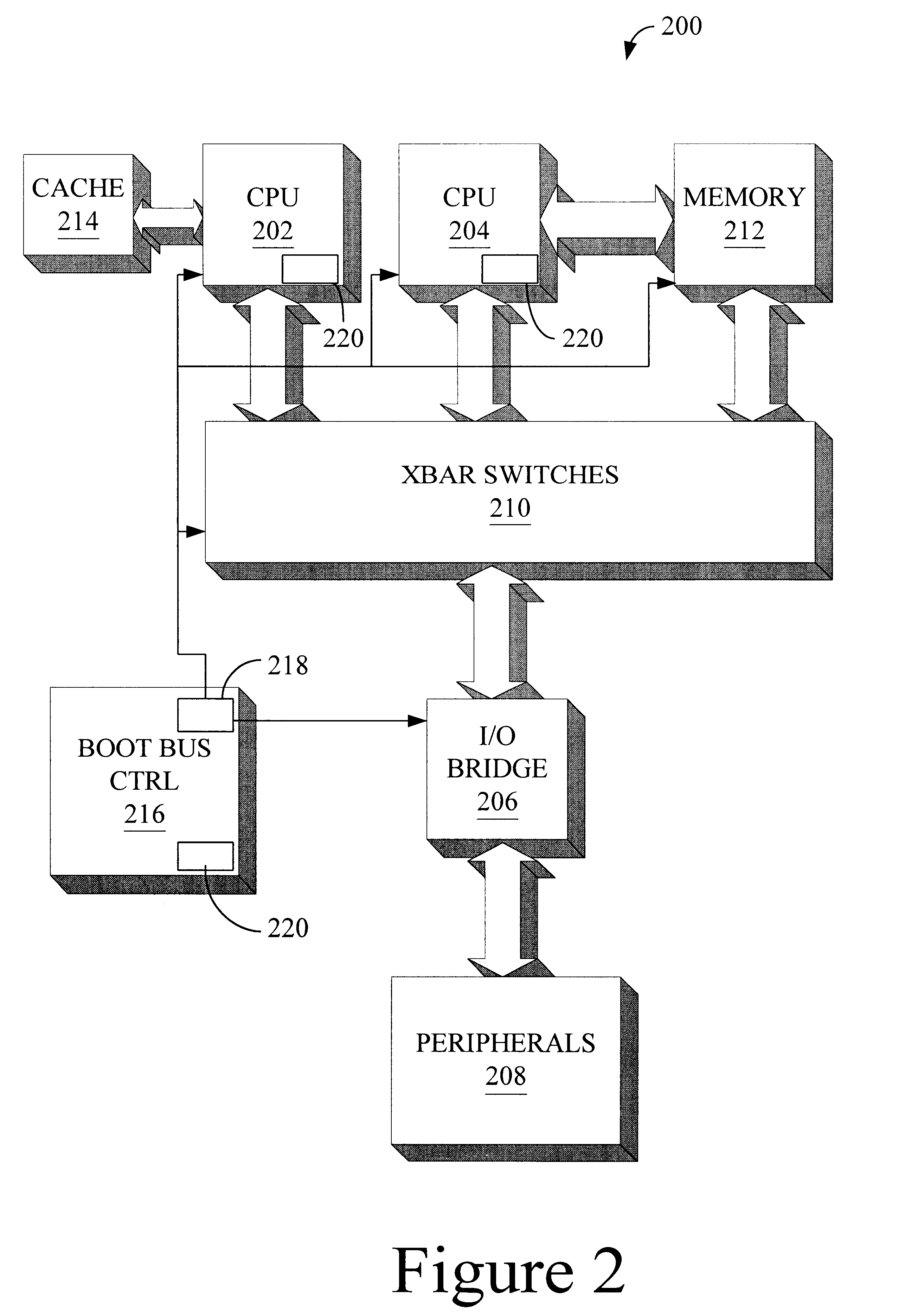
Illustrative embodiments of a method and apparatus for providing a multi-level, low-power mode of operation according to the present invention are shown in FIGS. 1-21. As will be readily apparent to those skilled in the art upon a complete reading of the present application, the presen...


PUM


Abstract

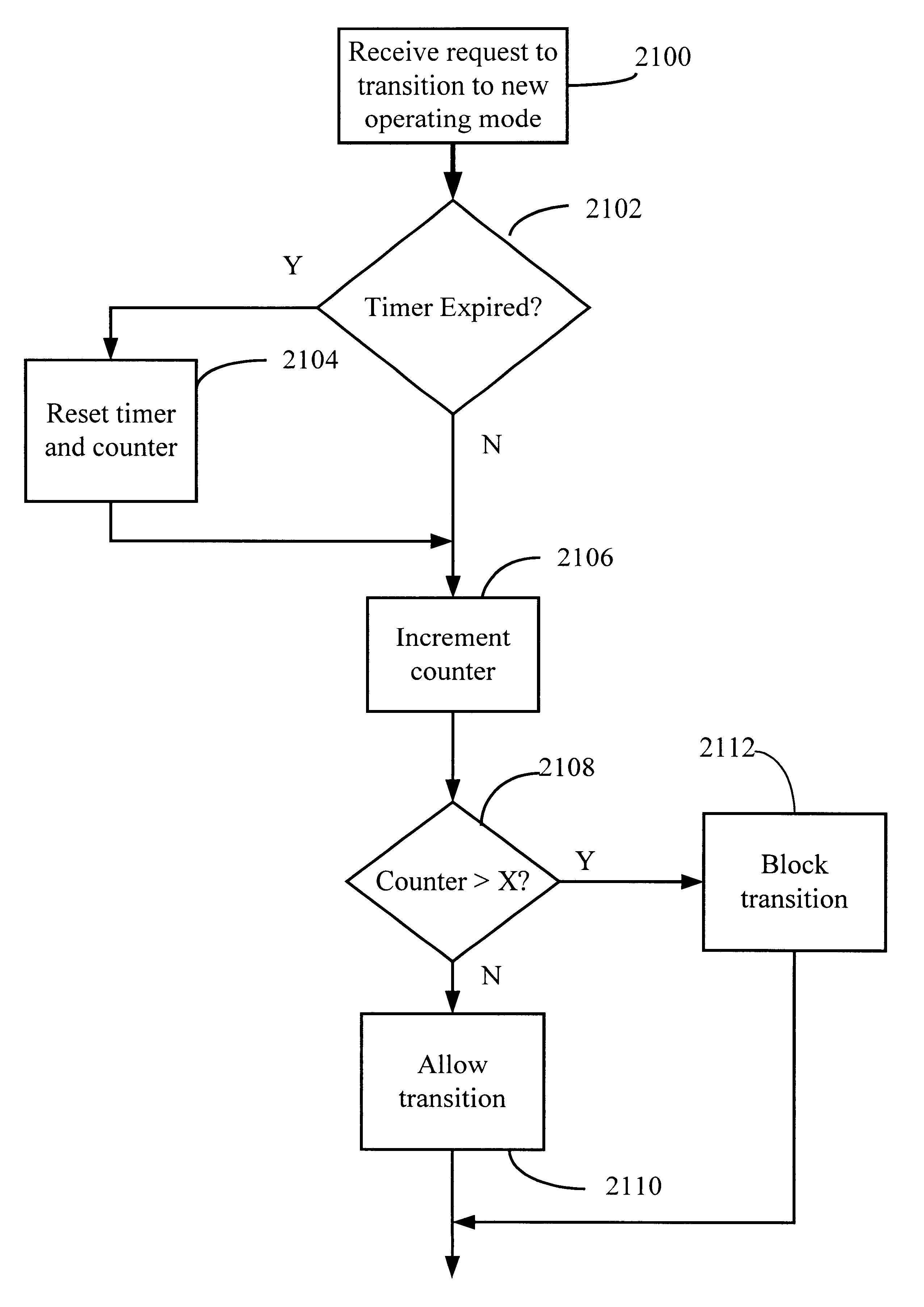
A method for controlling thermal cycles in a computer system is provided. The method is comprised of receiving a request to transition the computer system from a first operating mode to a second operating mode, where less power is consumed in the second operating mode. A historical rate at which the computer system has transitioned between the first and second operating modes is determined, and the requested transition is permitted in response to the historical rate being less than a first preselected setpoint, but denied in response to the historical rate being greater than the first preselected setpoint.

Description

1. Field of the InventionThis invention relates generally to low-power operating modes of electronic devices, and, more particularly, to a method and apparatus for transitioning between multiple power saving modes of operation.2. Description of the Related ArtFor a variety of reasons, power consumption has become an increasingly significant issue for electronic devices such as computer systems. First, the United States has promulgated a number of regulations regarding power usage or power savings. Further, since many electronic devices, such as laptop computers, draw power from a battery, reducing power consumption can result in significantly longer usage, making these electronic devices more versatile and useful. Additionally, power consumption is related to the amount of heat produced by the electronic device. Reducing power consumption reduces the amount of heat generated, and, thus, reduces the size and complexity of heat sinks, fans, and other structures used to help cool the e...

Claims


Application Information

Patent Timeline
Patent Type & Authority Patents(United States)
IPC IPC(8): G06F1/20G06F1/32G06F1/08
CPCG06F1/08G06F1/206G06F1/3203G06F1/324Y02B60/1217Y02B60/1275Y02D10/00
Inventor MIROV, RUSSELL N.CEKLEOV, MICHELYOUNG, MARKBALDWIN, WILLIAM M.
Owner ORACLE INT CORP
Learn More