System and method for controlling an automated fueling station

a fueling station and system technology, applied in liquid transfer devices, process and machine control, instruments, etc., can solve the problems of site controllers that may occasionally fail, operator of site cannot service his customers, and all of these devices are rendered useless

Inactive Publication Date: 2004-10-05
ALTAMETRICS AUTOGAS
View PDF12 Cites 37 Cited by
  • Summary
  • Abstract
  • Description
  • Claims
  • Application Information

AI Technical Summary

Problems solved by technology

For various reasons (for example, power supply failure, hard disk crash, motherboard failure, etc.), a site controller may occasionally fail.
That is, the operator of the site is unable to service his customers.
All of these devices are rendered useless if the central site controller fails.
Thus, a failure of a single dispenser controller affects only the fuel dispenser associated with the failed controller.

Method used


Image

  • System and method for controlling an automated fueling station
  • System and method for controlling an automated fueling station
  • System and method for controlling an automated fueling station

Examples


first embodiment

FIG. 6 is a simplified block diagram of the controller configuration of the present invention when implemented at a retail fueling station having six fuel dispensers 610-615. Each of the six dispensers is connected via a D-Link 620 and an I-Link 625 to one of six dedicated CPU controllers 630-635. The D-Link is a serial connection that enables the application programs in the controller to implement and maintain a dispenser message level protocol for controlling the fueling operation of the dispenser. The I-Link is a serial connection that enables the application programs to implement and maintain ICR message level protocols for controlling the island card reader and accepting customer payment for the fuel. Note that each of the dedicated CPU controllers may be physically implemented within each of the fuel dispensers. In this configuration, the D-Link and I-Link connections are internal to the dispenser, and only the H-Link is managed externally. The H-Link may also be implemented u...

second embodiment

FIG. 7 is a simplified block diagram of the controller configuration of the present invention which solves this problem by installing a Global Positioning System (GPS) receiver 650-655 with each CPU controller 630-635. Each GPS receiver receives signals transmitted from at least four GPS satellites and calculates a precise location for the receiver. This location information is then sent over the H-Link 645 to the host server 640. Thereafter, if a CPU controller fails, the physical location of the failed controller can be ascertained from the data received from the failed controller's associated GPS receiver.

third embodiment

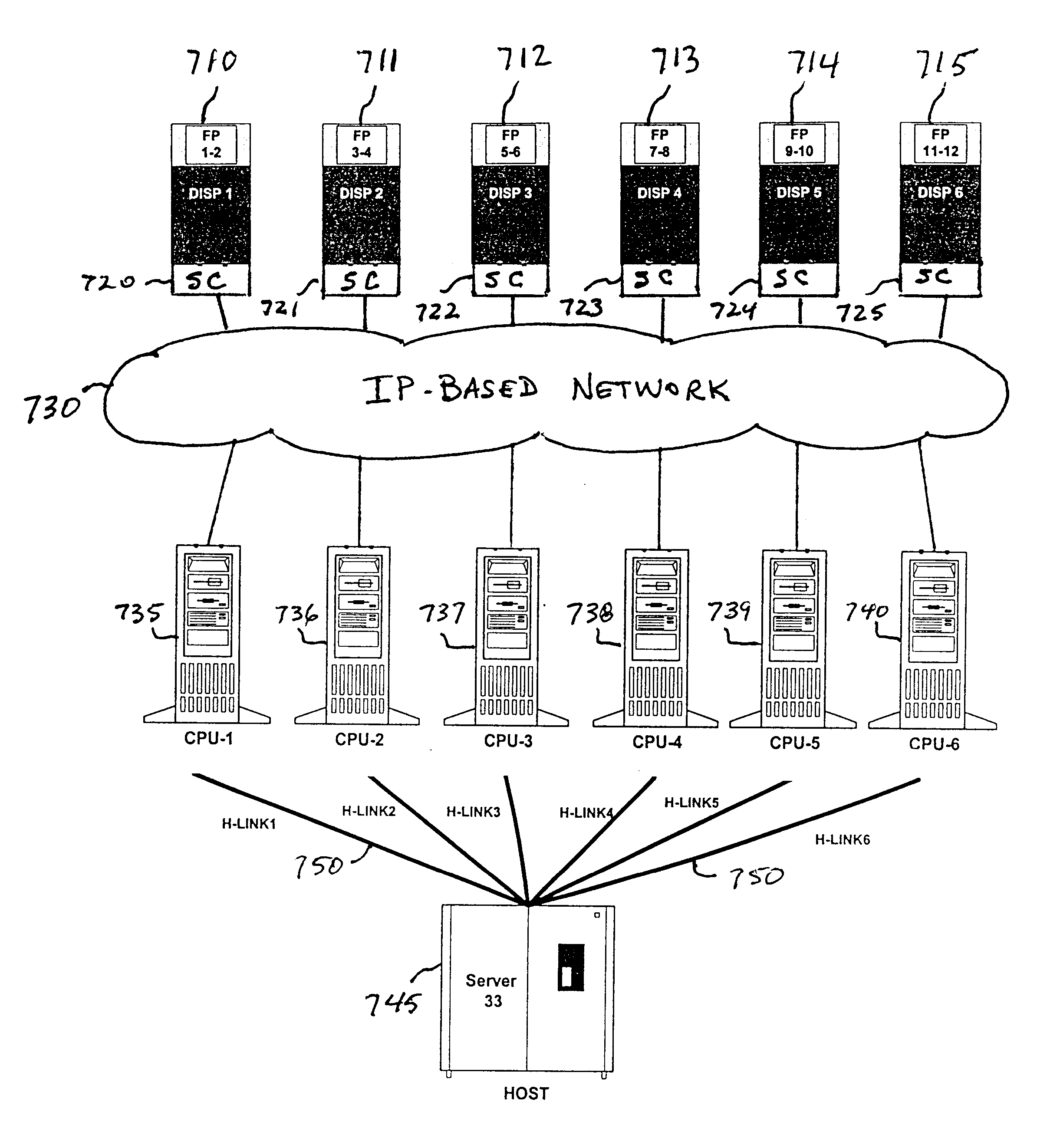
FIG. 8 is a simplified block diagram of the controller configuration of the present invention when implemented at a retail fueling station having six fuel dispensers 710-715. In this embodiment, each of the fuel dispensers includes a Signal Converter (SC) 720-725 that converts the Active Current Loop and RS-422 / 485 controlled transmitter circuits utilized for the D-Link and I-Link signaling into an Internet Protocol (IP)-based protocol such as Transaction Control Protocol / Internet Protocol (TCP / IP). Each of the dispensers then connects directly to an IP-based, connectionless packet data network 730. Each of the CPU controllers 735-740 also connects to the IP-based network, providing inter-connectivity between any one of the dispenser controllers and any one or more of the fuel dispensers. With appropriate addressing, any of the CPU controllers can thus communicate with and control any dispenser or combination of dispensers.

As in the first and second embodiments illustrated in FIGS. ...


PUM


Abstract

A system and method for controlling an automated fueling station having a plurality of fuel dispensers that accepting payment from a customer and dispense fuel. The system may perform consumer card authorizations utilizing a remote host server or a local database. A plurality of dispenser controllers are located at the fueling station, and each of the controllers is associated with and controls one of the dispensers. Each of the dispenser controllers includes a network connection to the server or local database for accessing consumer card authorization information. A failure of a single dispenser controller affects only the fuel dispenser associated with the failed controller. In another embodiment, the dispenser controllers are connected to the fuel dispensers through an Internet Protocol (IP)-based network that enables any controller to control any dispenser or combination of dispensers.

Description

1. Technical Field of the InventionThis invention relates to distributed data networks. More particularly, and not by way of limitation, the present invention is directed to a system and method for controlling an automated fueling station utilizing distributed controllers.2. Description of Related ArtData networks today may be distributed over wide areas, with a plurality of site locations being linked together over the network. Each of the distributed sites is typically controlled by a site controller or central processing unit (CPU) such as a personal computer (PC). For various reasons (for example, power supply failure, hard disk crash, motherboard failure, etc.), a site controller may occasionally fail. Currently, whenever a site controller fails, a network operator must locate an available service technician (and parts) to travel to the site to repair or replace the failed controller. During this time, the entire site is out of business. That is, the operator of the site is una...

Claims


Application Information

Patent Timeline
Patent Type & Authority Patents(United States)
IPC IPC(8): B67D5/08B67D5/14G07F13/00G07F15/00G07F5/00G07F13/02G07F7/12G07F5/18B67D7/14
CPCB67D7/14G06Q50/06G07F5/18G07F15/00G07F7/12G07F11/002G07F13/025G07F7/08G07F9/002
Inventor COVINGTON, STEVEASHBY, DAVID
Owner ALTAMETRICS AUTOGAS
Why Eureka
Try Eureka