Lighting security system

a security system and lighting technology, applied in the field of security systems, can solve the problems of not economically integrating a variety of available technologies and security techniques, and no security systems are presently availabl

Inactive Publication Date: 2004-11-16
BINGHAM VICTORIA J
View PDF27 Cites 46 Cited by
  • Summary
  • Abstract
  • Description
  • Claims
  • Application Information

AI Technical Summary

Benefits of technology

Yet another aspect of the invention is to provide a method of effecting lighting security including providing a plurality of light packs, each light pack having at least two light sources, a plurality of motion sensors, an imaging unit, an electric eye, a lens, a processing element, a timer, and a power source; positioning each light pack to monitor an associated designated area for movement of an object within the associated designated area; monitoring each designated area with the corresponding associated light pack for movement of an object in the associated designated area; activating each light of one light pack in predetermined directions upon detection of movement of an object in the designated area of the one light pack, one of the predetermined directions being toward another one of the plurality of light packs; successively activating each light of another light pack of the plurality of light packs until each light pack is activated; and recording at least one image of at least one designated area with at least one imaging unit of at least one light pack.
It is an aspect of the invention to provide improved elements and arrangements thereof in a lighting security system for the purposes described which is inexpensive, dependable and fully effective in accomplishing its intended purposes.

Problems solved by technology

However, no security systems are presently available that economically integrate a variety of available technologies and security techniques.

Method used


Image

  • Lighting security system
  • Lighting security system
  • Lighting security system

Examples


Embodiment Construction

The present invention is a lighting security system. The invention disclosed herein is, of course, susceptible of embodiment in many different forms. Shown in the drawings and described hereinbelow in detail are preferred embodiments of the invention. It is to be understood, however, that the present disclosure is an exemplification of the principles of the invention and does not limit the invention to the illustrated embodiments.

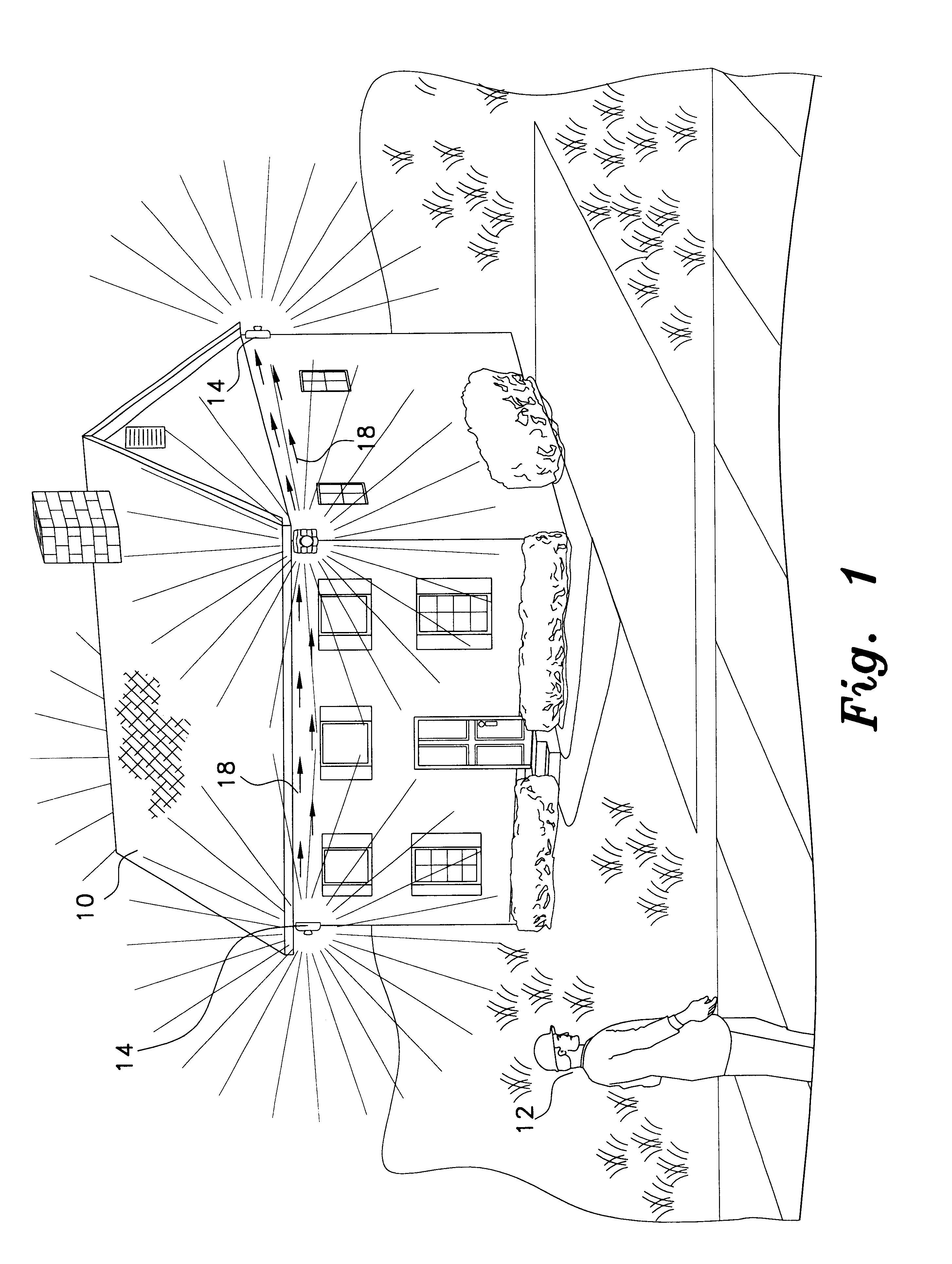
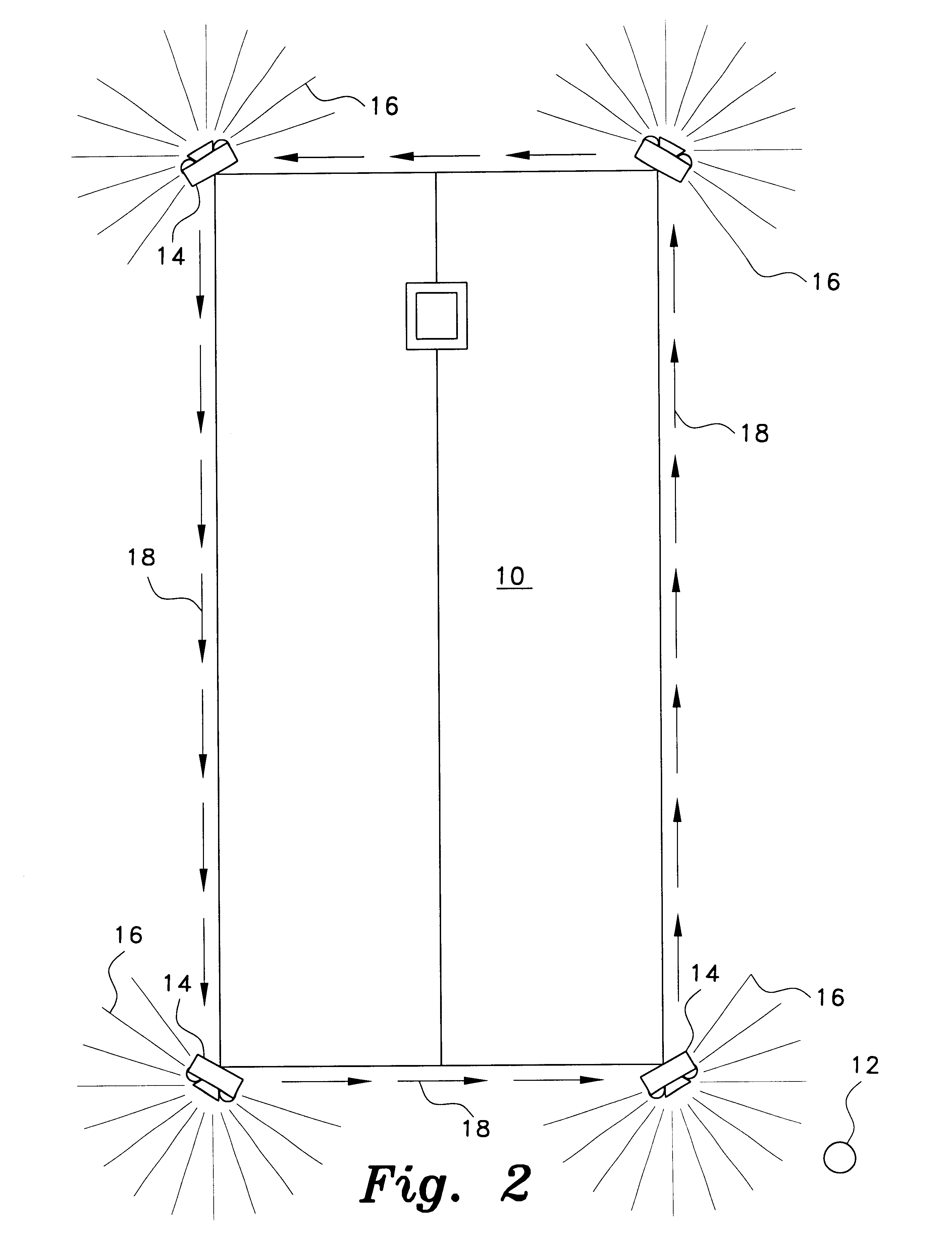
Referring to the drawings, FIGS. 1 and 2 illustrate a residential home 10 equipped with a lighting security system according to the invention. In FIGS. 1 and 2, the lighting security system includes four light packs 14. Each light pack 14 includes a light source 16 which emits light upon detection of disturbance by an individual 12. Upon detection of the disturbance, the light pack 14 which detected the disturbance emits light directed 18 directed toward another light pack 14 within a brief period of time, such as microseconds or less. To the intruder 12, t...


PUM


Abstract

A lighting security system includes a plurality of light packs. Each light pack includes at least two light sources, a plurality of motion sensors, an imaging unit, an electric eye, a lens, a processing element, a timer, and a power source. Upon detection of movement of an object in a designated area of a light pack, each light of the light pack activates and successively activates the other light packs of the plurality of light packs until all of the light packs are activated. Each light pack may also include one or more switches, an audible indicator, a modem configured to wirelessly or non-wirelessly transfer data to/from the light pack. If a light pack is configured for wireless data transfer, the light pack will also include a transceiver and an antenna.

Description

BACKGROUND OF THE INVENTION1. Field of the InventionThe present invention relates generally to security systems, and more particularly to security systems that economically integrate a new variety of known technologies and security techniques.2. Description of the Related ArtSecurity systems presently exist that monitor residential and business properties, and activate deterrent devices, such as lights, alarms, etc., upon detecting disturbances, particularly near entryways to homes or buildings between dusk and dawn. Such security systems employ a variety of sensors such as passive infrared (PIR) motion detectors, mechanical switches, pressure pads, etc. to trigger the deterrent devices. Security systems also exist that employ video cameras to record particular areas. These video cameras are either configured to continuously record the area or to periodically capture a few seconds of time of the area. However, no security systems are presently available that economically integrate a...

Claims


Application Information

Patent Timeline
Patent Type & Authority Patents(United States)
IPC IPC(8): G08B15/00G08B13/00G08B13/196
CPCG08B13/19695G08B13/19645G08B13/19673G08B13/19628F21S8/033F21V23/0442
Inventor BINGHAM, VICTORIA J.
Owner BINGHAM VICTORIA J
Why Eureka
Try Eureka