Video encoding apparatus and video encoding method

a video encoding and video technology, applied in the field of picture encoding apparatus and picture encoding method, can solve the problems of circuit scale and consumption power increase, delay in signal process, and increase in the consumption power of this apparatus

Inactive Publication Date: 2004-11-16
KK TOSHIBA
View PDF22 Cites 7 Cited by
  • Summary
  • Abstract
  • Description
  • Claims
  • Application Information

AI Technical Summary

Benefits of technology

It is an object of the present invention to provide a picture coding apparatus and picture coding method, which can estimate a stuffing size of data to be coded before variable-length coding, and can code the data to be coded by stuffing.
It is another object of the present invention to provide a picture coding apparatus and picture coding method, which can output a predetermined bitstream without an increase in circuit scale and generation of any delay, since variable-length coding is done after stuffing into data to be coded.
In the present invention, since new circuits and processes to be added to implement stuffing for preventing buffer underflow in a decoding apparatus can be minimized, consumption power can be suppressed, and real-time processing can be maintained.

Problems solved by technology

In order to stuff MB into a bitstream, a memory serving as a buffer is required, and the consumption power of this apparatus increases.
Since a device must be added, the circuit scale and consumption power increase, thus generating a delay in the signal process.

Method used


Image

  • Video encoding apparatus and video encoding method
  • Video encoding apparatus and video encoding method
  • Video encoding apparatus and video encoding method

Examples


Embodiment Construction

A picture coding apparatus according to an embodiment of the present invention will be described hereinafter with reference to the accompanying drawings.

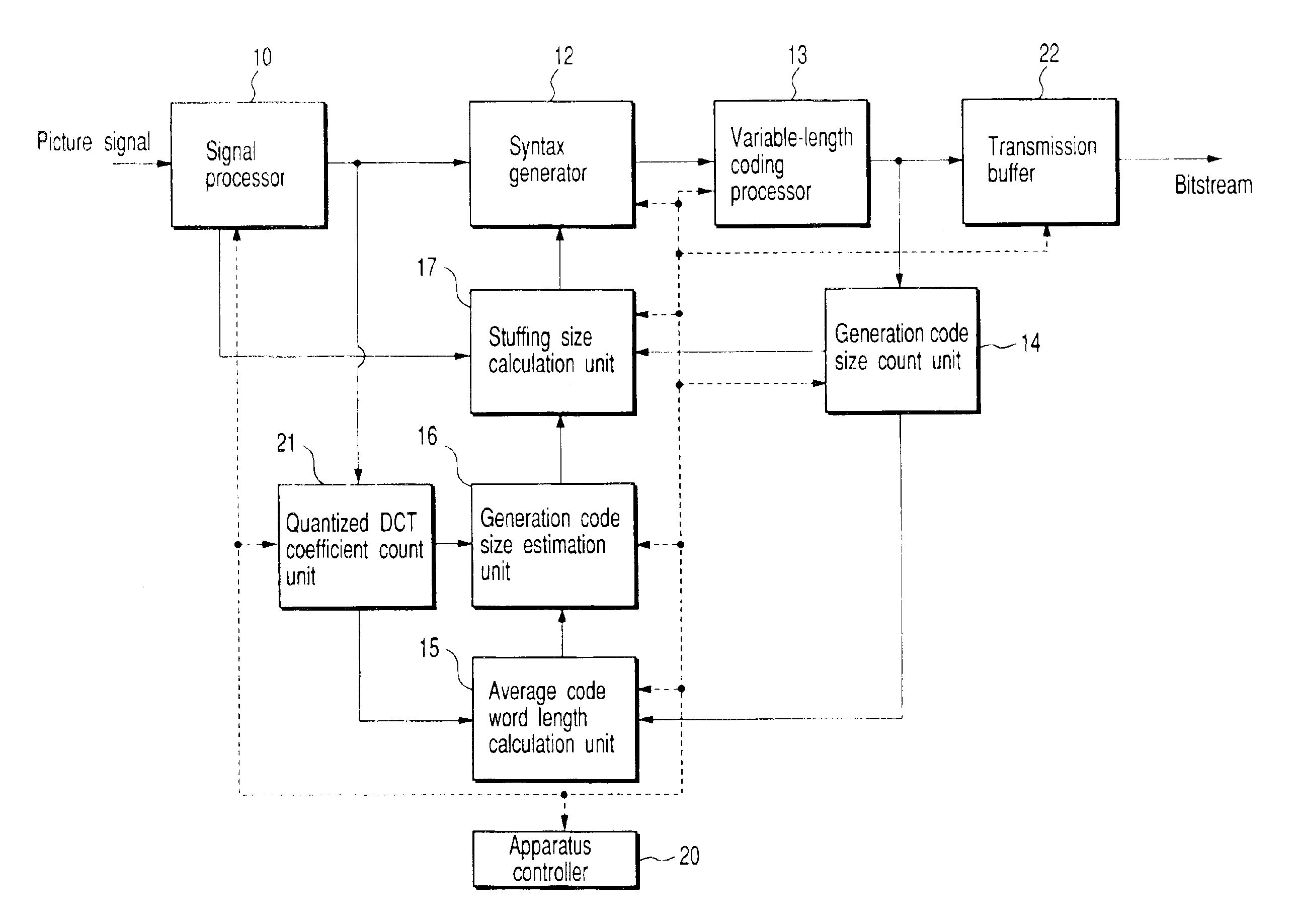
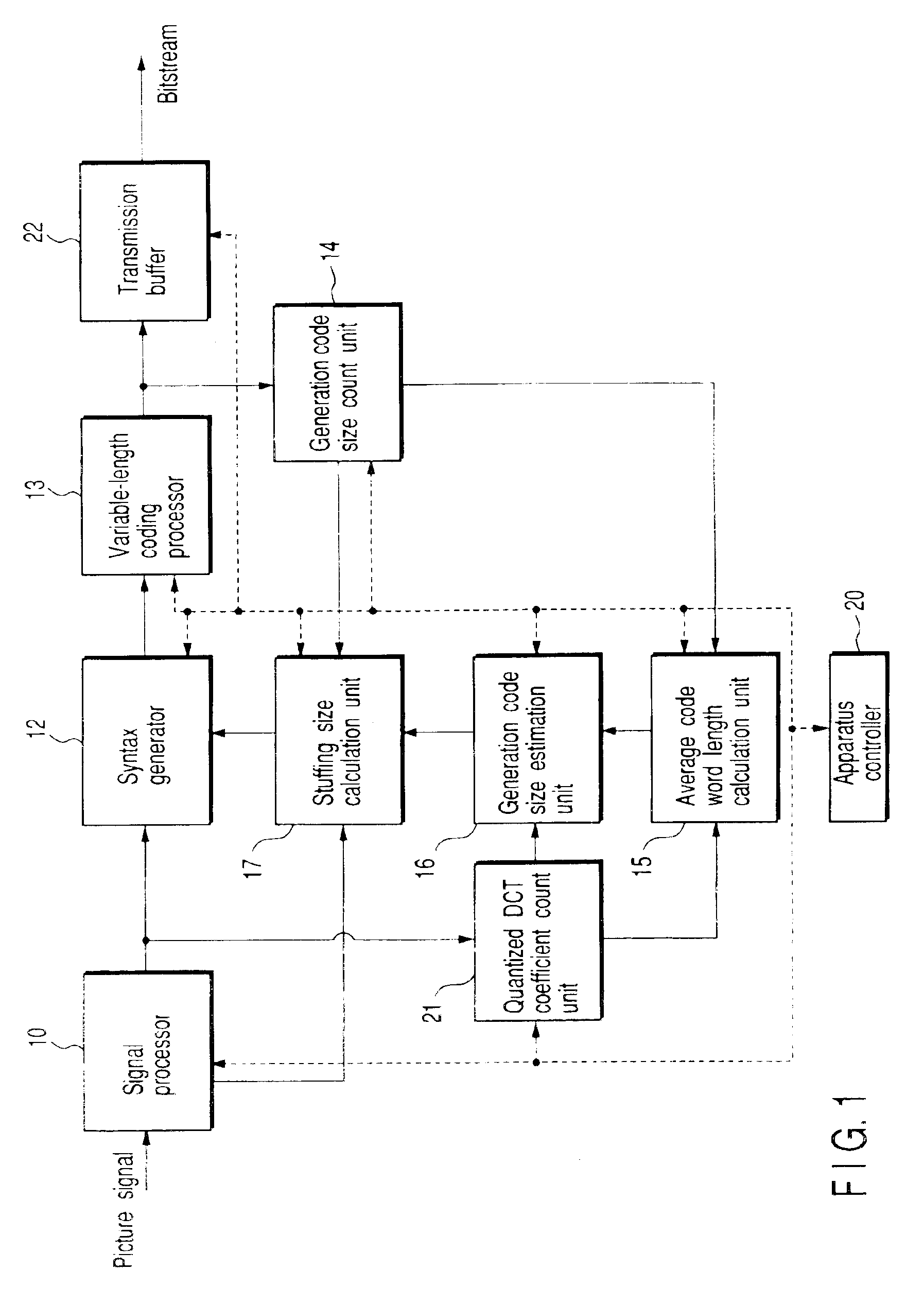
FIG. 1 is a block diagram of a picture coding apparatus for executing variable-length coding of a picture signal, i.e., a video signal, according to an embodiment of the present invention. The apparatus shown in FIG. 1 comprises an apparatus controller 20 for controlling respective units in this apparatus, and a signal processor 10 for segmenting a digital picture signal which is input in units of video object planes (VOP), or additionally, in units of frames or fields into predetermined blocks, i.e., macro-blocks MB in accordance with a predetermined picture signal compression scheme (MPEG-4, ITU-T recommendation H.263, or their modified schemes), and compressing the macro-blocks by executing a signal process.

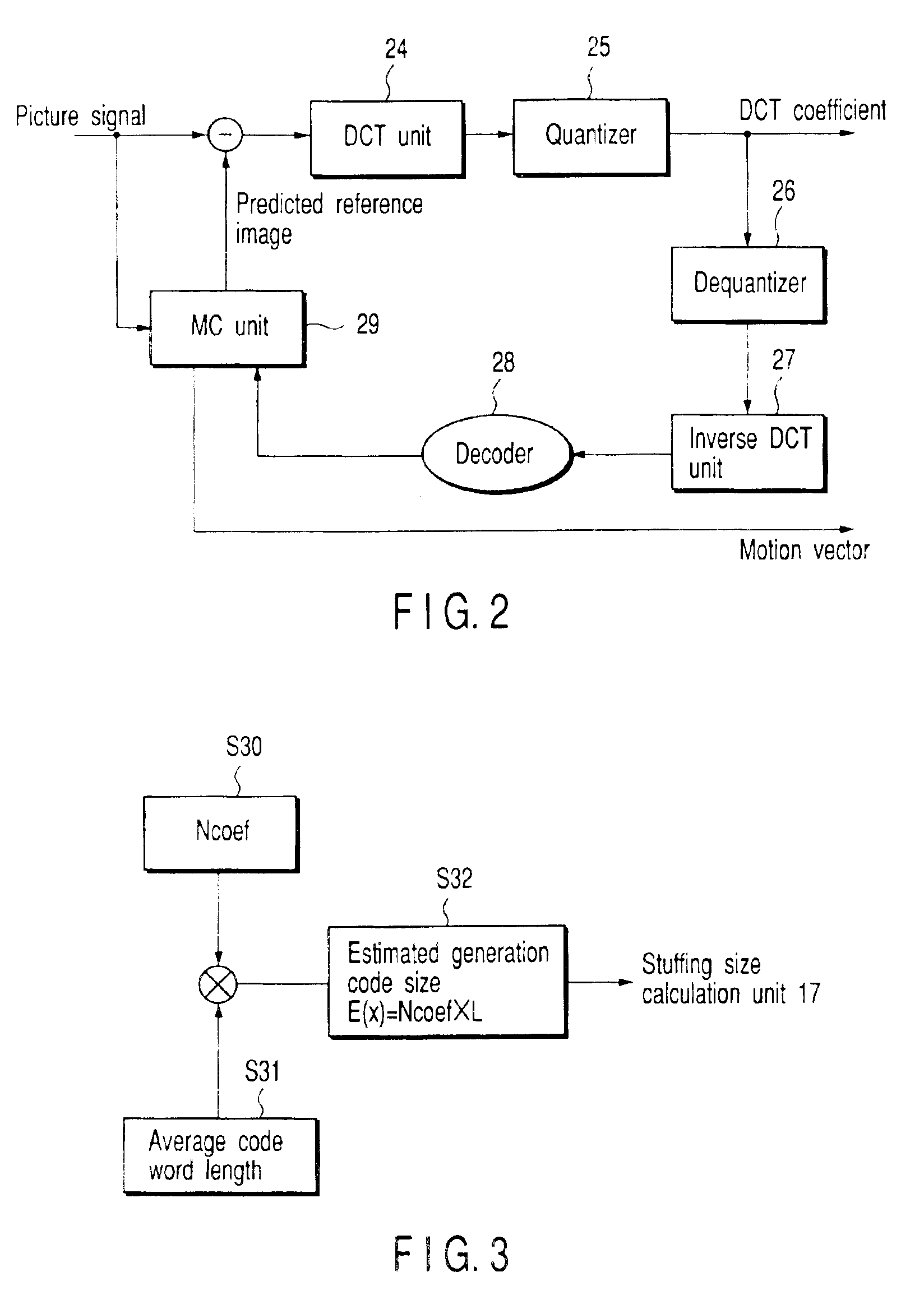
As shown in FIG. 2, the signal processor 10 comprises a quantized DCT coefficient (Discrete Cosine Transform) unit 24 and qu...


PUM


Abstract

A picture coding apparatus has a signal processor 10 for generating macro-block information by calculating and quantizing the DCTs of a picture signal of a given unit are calculated for each macro-block MB. This information is input to a syntax generator 12 to generate syntax, which is coded by a variable-length coding processor 13. Quantized DCT coefficients of macro information before coding are counted by a count unit 21, and a code size after coding the macro-block information is counted by a count unit 14. A calculation unit 15 calculates an average code length from the accumulated value of the two code sizes. An estimation unit 14 estimates a generation code size after coding given macro-block information input to the syntax generator 12 on the basis of the average code size. A calculation unit 17 calculates a stuffing size by comparing the estimated generation code size with an actually generated generation code size, and the syntax generator 12 generates syntax on the basis of this stuffing size and macro-block MB information.

Description

The present invention relates to a picture coding apparatus for coding a digital moving image signal and, more particularly, to a picture coding apparatus for stuffing predetermined bits into a signal-processed bitstream upon executing the signal process of a picture signal of, e.g., a digital moving image or the like by a predetermined coding scheme.In general, a picture coding apparatus for coding a video signal, i.e., a picture signal, must code the picture signal by a predetermined scheme to segment it into units each having a predetermined code size, and must output bitstreams having this unit. That is, in order to prevent a buffer in a decoding apparatus on the receiving side that receives bitstreams from overflowing or underflowing, an coding apparatus on the output side of bitstreams is required to control the code size of each bitstream. As a general method for preventing overflow, control of quantization parameters, control of coding frames, and the like are available, and...

Claims


Application Information

Patent Timeline
Patent Type & Authority Patents(United States)
IPC IPC(8): G06T9/00H04N7/24H04N7/26H04N7/50H04N7/30H04N19/115H03M7/30H03M7/40H04N19/134H04N19/146H04N19/15H04N19/176H04N19/196H04N19/423H04N19/46H04N19/60H04N19/625H04N19/70H04N19/91H04N21/234H04N21/2343H04N21/236H04N21/44
CPCH04N21/23406H04N21/234354H04N21/23611H04N19/91H04N19/70H04N19/61H04N19/60H04N21/44004
Inventor KAWASHIMA, YUJIASANO, ATSUSHI
Owner KK TOSHIBA
Why Eureka
Try Eureka