Catheter information ring

a technology of information rings and catheters, applied in the field of catheters, can solve the problems of text applied to extension tubes that are susceptible to rubbing off, and the text size and clarity are limited

Inactive Publication Date: 2004-11-30
MEDICAL COMPONENTS INC
View PDF16 Cites 65 Cited by
  • Summary
  • Abstract
  • Description
  • Claims
  • Application Information

AI Technical Summary

Problems solved by technology

However, one drawback to this approach is that text size and clarity is limited, since the extension tubes are tubular and are typically translucent.
Additionally, the text applied to the extension tubes is susceptible to rubbing off over time.

Method used


Image

  • Catheter information ring
  • Catheter information ring
  • Catheter information ring

Examples


first embodiment

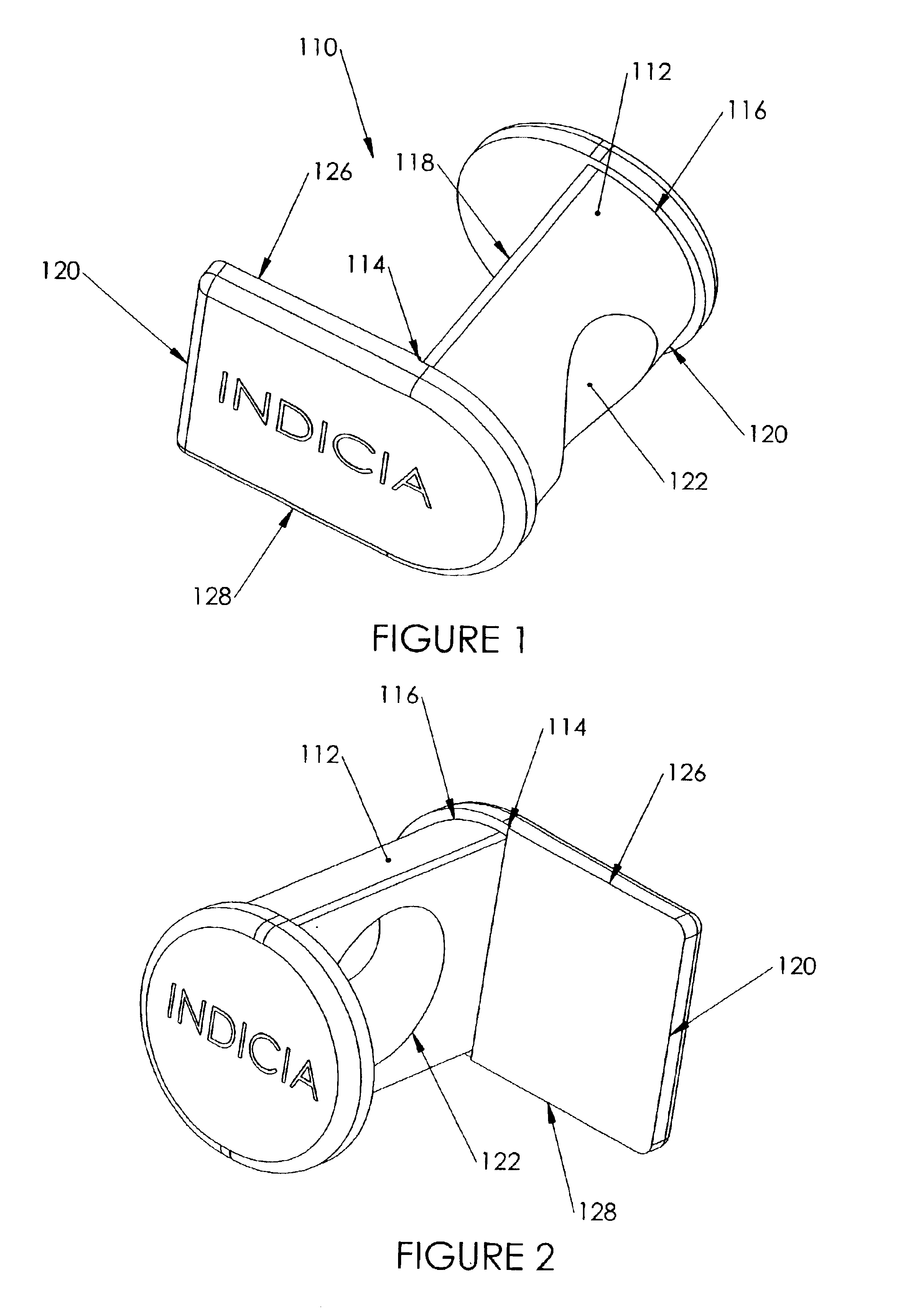
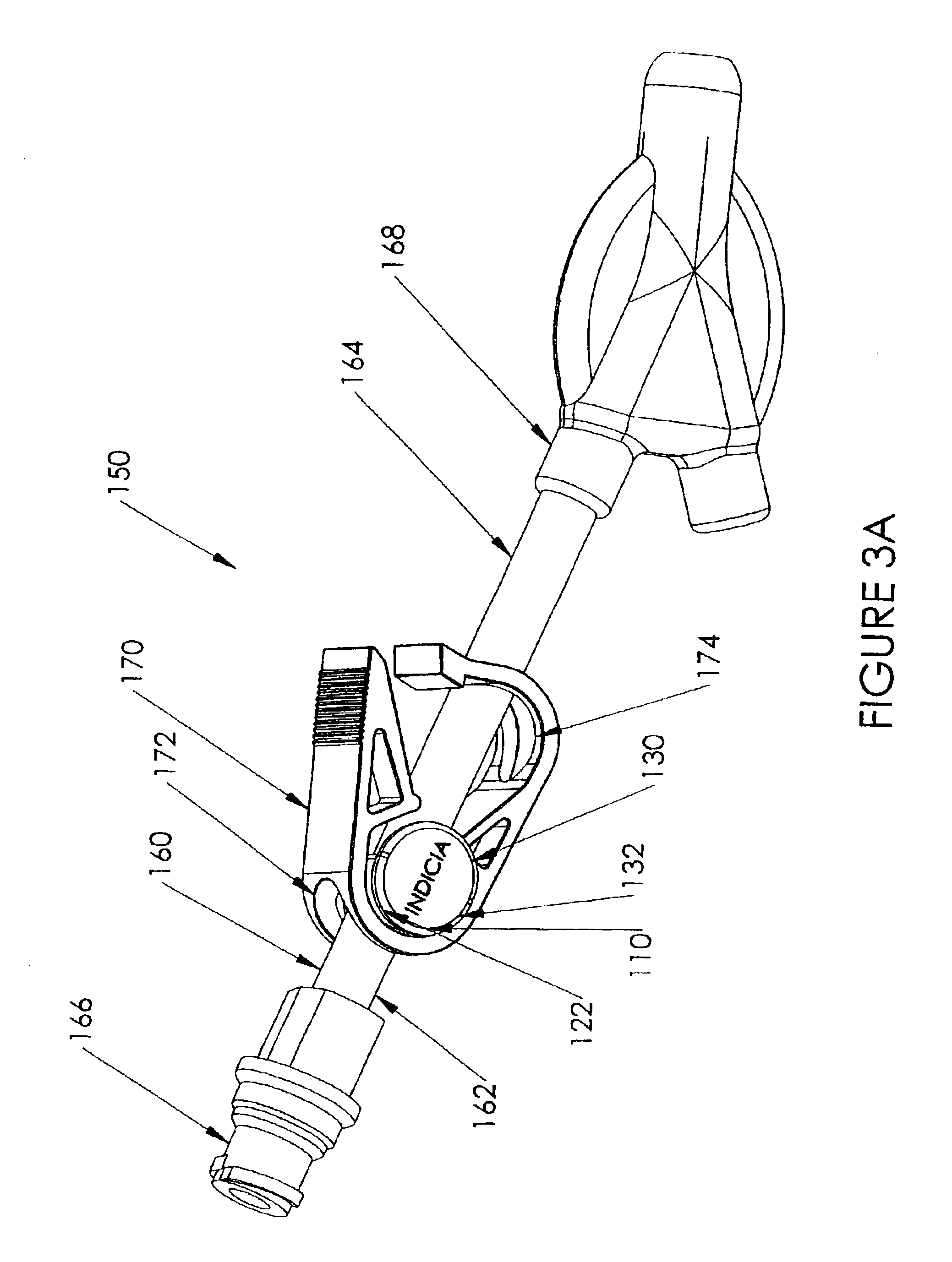
an information ring 110 for use with a catheter according to the present invention is shown in FIGS. 1 and 2. The information ring 110 includes a body 112 having a first end 114 and a second end 116. A generally planar first face 118 extends between the first end 114 and the second end 116. A second face 120, preferably generally rounded, extends between the first end 114 and the second end 116. A generally circular opening 122 extends through the body 112 between the first face 118 and the second face 120. A generally elongated first indicia portion 124, which is located at the first end 114 of the body 112, includes an indicia face 128, on which identifying indicia is printed. As can be seen from FIG. 1, the first indicia portion 124 extends generally orthogonally from the first face 118, although those skilled in the art will recognize that the first indicia portion 124 may extend other than orthogonally from the first face 118. A second indicia portion 130 is located at the seco...

second embodiment

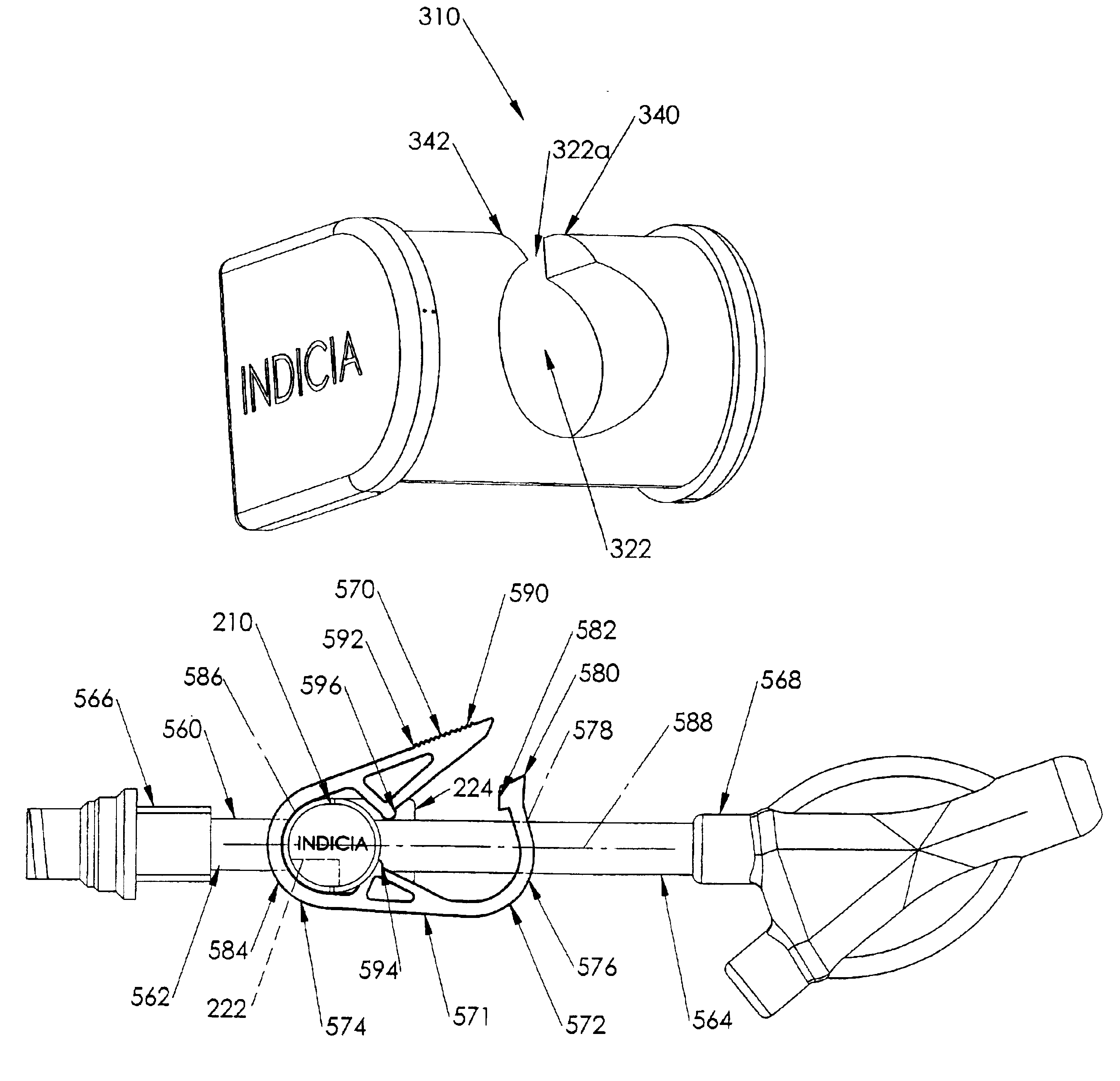
an information ring 210 according to the present invention is shown in FIGS. 4 and 5. The information ring 210 includes a body 212 having a first end 214 and a second end 216. A first face 218 extends between the first end 214 and the second end 216. Preferably, the first face 218 is generally planar, although those skilled in the art will recognize that the first face 218 may be other than planar. A generally rounded second face 220 extends between the first end 214 and the second end 216. A generally U-shaped channel 222 extends through the body 212 between the first face 218 and the second face 220. The channel 222 has an open portion 222a. The semi-circular closed portion 222b extends generally parallel to a longitudinal axis of the conduit over which the information ring 210 is disposed, and a generally semi-circular closed portion 222b opposing the open portion 222a. A first indicia portion 224 is located at the first end 214 of the body 212, and includes an indicia face 228, ...

third embodiment

an information ring 310 according to the present invention is shown in FIGS. 6 and 7. The information ring 310 is similar to the information ring 210 as described above, but with a pair of tabs 340, 342 that extend from the body 312 toward each other partially across the open portion 322a of the channel 322. Although two tabs 340, 342 are shown, those skilled in the art will recognize that only one tab 340 need be used.


PUM


Abstract

An information ring for use with a catheter is disclosed. The information ring includes a body having a first end and a second end. The body has a first body face extending between the first end and the second end, and a second, generally convex face extending between the first end and the second end. The body has an opening extending therethrough between the first body face and the second face. A first indicia portion is located at the first end. The first indicia portion has a first indicia face sized to allow indicia to be printed on the first indicia face.

Description

Catheters for the introduction or removal of fluids may be located in various venous locations and cavities throughout the body for the introduction or removal of such fluids. Such catheterization may be performed by using a single catheter having multiple lumens. A typical example of a multiple lumen catheter is a dual lumen catheter in which a first lumen introduces fluids and a second lumen removes fluids. These catheters are very useful for procedures such as hemodialysis, wherein blood is removed from a patient through the first lumen for processing in a hemodialysis machine, and the processed blood is returned to the patient through the second lumen. Alternatively, multiple catheters, each having a single lumen, may be inserted in multiple locations in the patient, such as in each femoral vein.Catheters are manufactured in different sizes and from different materials depending on the circumstances of their use. For example, smaller catheters are used on smaller patients, and d...

Claims


Application Information

Patent Timeline
Patent Type & Authority Patents(United States)
IPC IPC(8): B65D83/08B65D83/10G09F3/00G09F3/08G09F3/10G09F3/16A61MA61M1/14A61M25/00A61M39/28G09F3/02G09F3/20
CPCA61M39/284G09F3/205G09F3/16G09F3/0295A61M2205/60
Inventor SCHWEIKERT, TIMOTHY
Owner MEDICAL COMPONENTS INC
Why Eureka
Try Eureka