Optical reader comprising multiple color illumination

a technology of optical readers and illumination elements, applied in the direction of electromagnetic radiation sensing, exposure control, instruments, etc., can solve the problems of not being able the structure of the illumination element and the structure supporting it consumes substantial space, and the laser based imaging module is not well adapted to capture 2d images

Inactive Publication Date: 2004-12-21
HAND HELD PRODS
View PDF116 Cites 1124 Cited by
  • Summary
  • Abstract
  • Description
  • Claims
  • Application Information

AI Technical Summary

Benefits of technology

In a still further aspect of the invention, a module according to the invention can include aiming and illumination light sources having improved architectures. Light sources incorporated in the module can include surface integrated LEDs in which part of the light source is defined by a printed circuit board. Use of surface integrated LEDs in a module appropriately configures substantially reduces a dimension of the module in at least one plane. The module can also incorporate side leaded surface mount LEDs which can be firmly benched against a printed circuit board to achieve precision alignment of the LEDs without additional aligning members or alignment aiding assembly steps.
With the significant miniaturization achievable with module architectures according to the invention, the module can readily be fittable into instrument or device housings of small size which become optical readers with the module installed therein. Modules according to the invention can be installed for example in gun style reader housings, personal data assistants (PDAs), portable data terminals (PDTs), mobile telephones, calculators, wrist watches, finger worn "ring scanners," writing implements such as pens, and numerous other devices.

Problems solved by technology

The built in illumination elements and structural members supporting them consume substantial space.
Certain problems have been noted with laser based imaging modules, however.
First, laser based imaging modules are not well adapted to capture 2D images and therefore cannot be utilized in a system for decoding certain types of 2D indicia such as 2D matrix bar codes and OCR characters.
Although existing laser based imaging modules read stacked 2D symbologies such as PDF417, they typically are not appropriate for the capture of 2D images.
Attempts to adapt a laser scanner based image engine for 2D image capture have been unsuccessful.
Laser scanning 2D image engines, while generating low resolution image signals, have been observed to be costly, and space consuming.
Another major problem noted with laser based bar codes is their lack of durability.
Laser scan engine modules require a moving mirror which is delicately mounted.
Mirror mount structure can easily be misaligned or broken by sudden impact of a housing incorporating the module on a rigid object.
The mechanical complexity of a laser scanner based imaging module increases significantly if the module must generate 2D image signals.
First, as mentioned, laser scanner based imaging modules, because of their limited functionality can easily be made in packages of reduced size and weight.
Diffractive mold element 528 is costly to manufacture, and requires frequent replacement.

Method used


Image

  • Optical reader comprising multiple color illumination
  • Optical reader comprising multiple color illumination
  • Optical reader comprising multiple color illumination

Examples


example 1

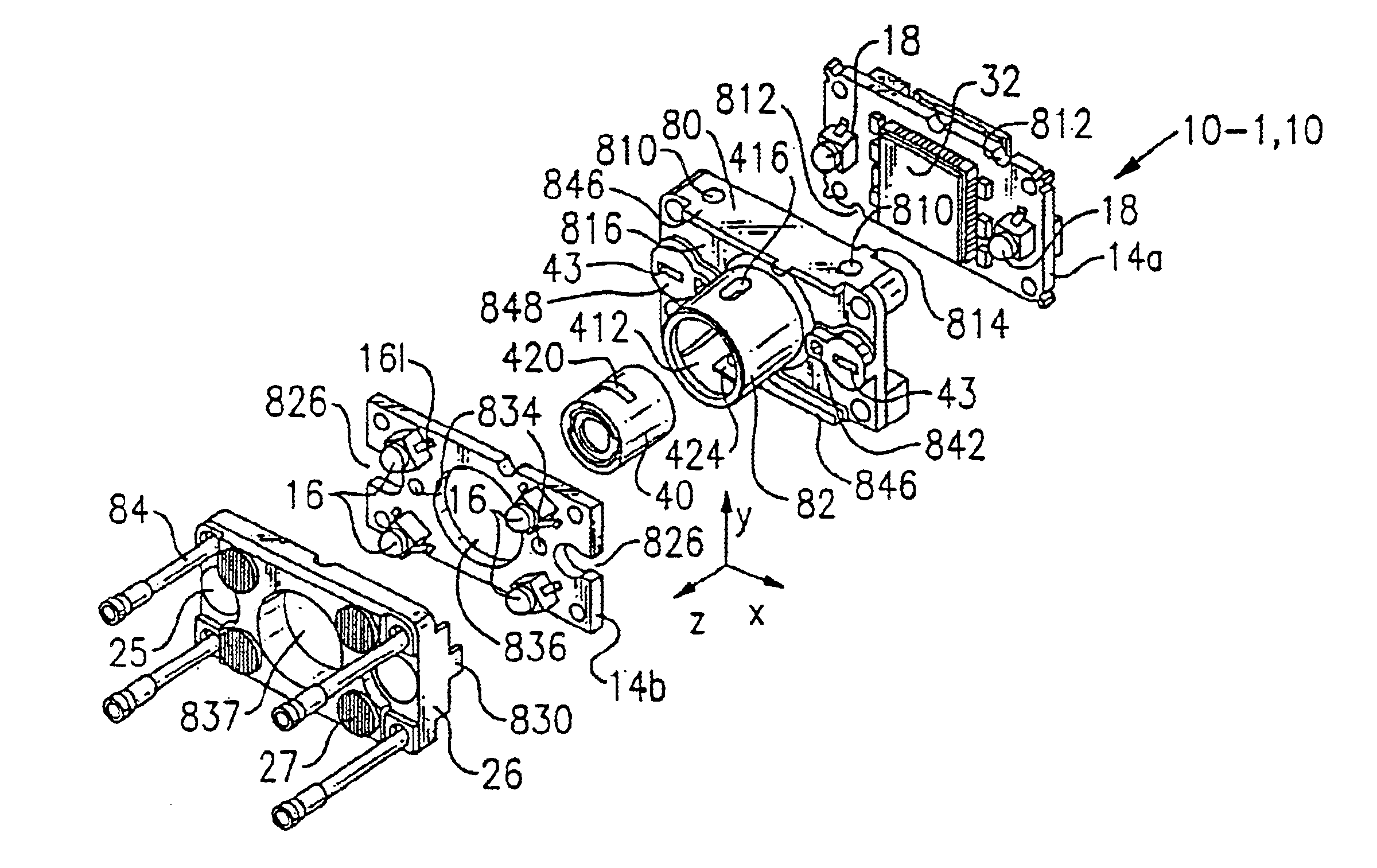
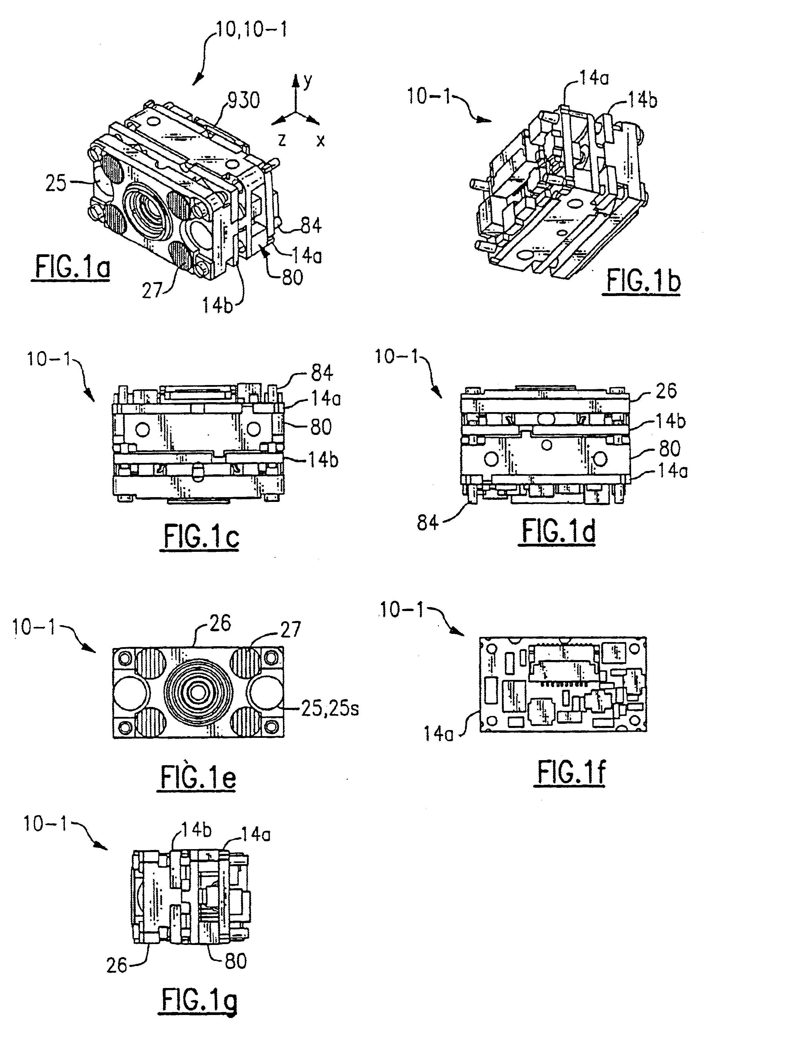
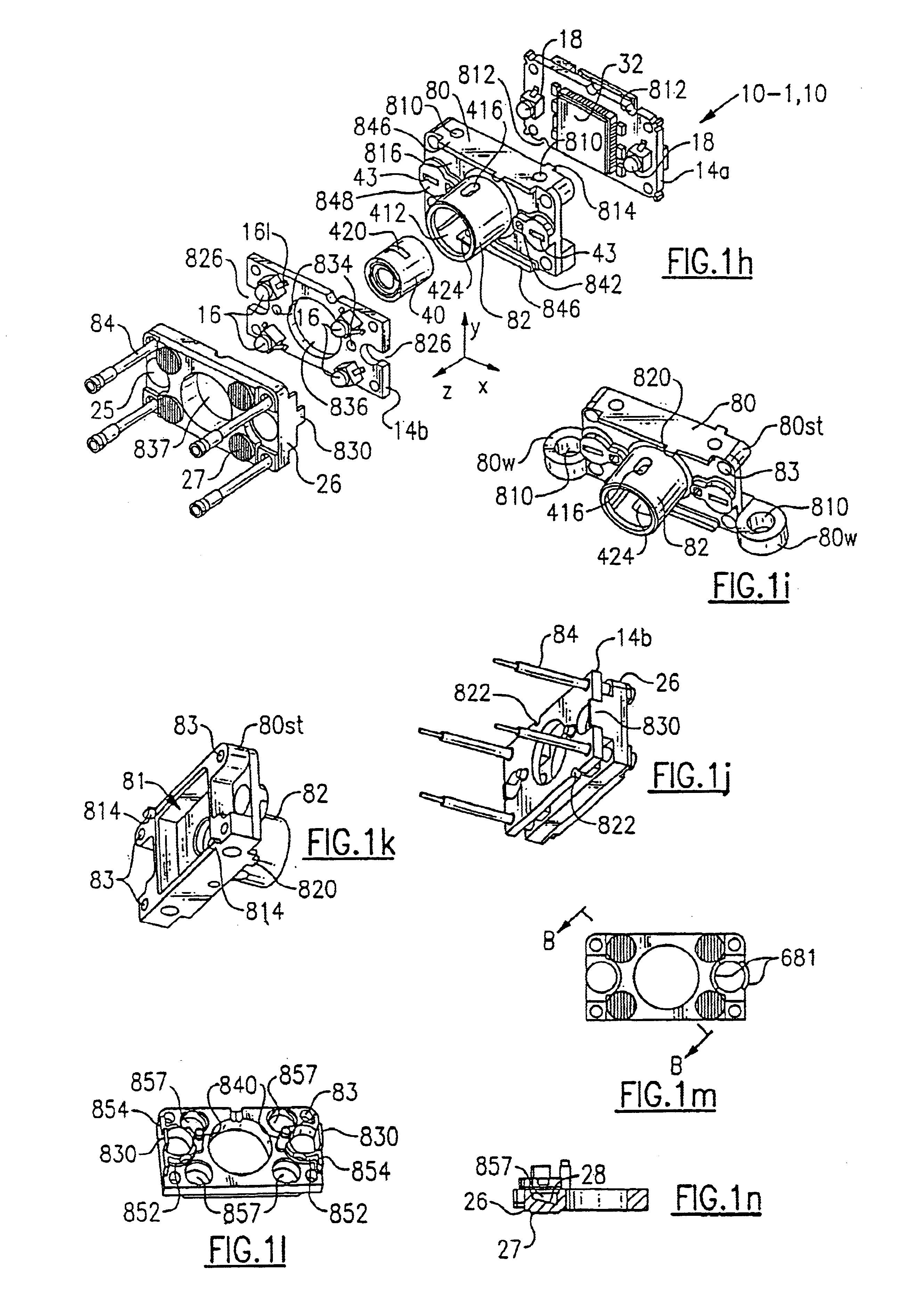
An aiming pattern generation system 685 comprising a pair of aiming LEDs 18, a pair of apertures 43, and a pair of spherical lens 25s substantially as shown in FIG. 1h is designed such that each half of the aiming pattern generating system has the properties as presented in Table 1.

Aiming system 685 generates aiming pattern light rays substantially as is illustrated in the computer modeled side view of system 685 of FIG. 6z. It is seen that the small size of aperture 43 substantially prevents light rays from reaching borders 686 of lens 25s in the vertical plane (aiming light rays may reach borders 686 in the horizontal plane, thus the lens aperture effect described with reference to FIG. 6y may apply in the horizontal plane). Instead the bundle of light rays emanating from aperture 43 are substantially concentrated so that they are incident on the lens member including lens surface 25s toward a center (axis) of the lens member in the vertical plane. Although an imaging plane for th...


PUM


Abstract

An imaging module in one embodiment includes at least one multiple color emitting light source comprising a plurality of different colored LED dies each independently driveable so that the overall color emitted by the light source can be controlled and varied. The multiple color emitting light source can be controlled so that the color emitted by the light source is optimized for imaging or reading in a present application environment of the module. Further, the module can be configured so that control of the multiple color emitting light source automatically varies depending on a sensed condition, such a color present in a field of view of the module, the distance of the module to a target, and / or a predetermined criteria being met so that feedback is provided to a user. The module in a further aspect can include illumination light sources and aiming light sources which project light in different wavelength emission bands.

Description

The invention relates to optical readers in general and specifically to an optical reader imaging module which emits light in more than one visible color wavelength band.BACKGROUND OF THE PRIOR ARTMost image signal generating data collection devices require built-in illumination elements for illuminating a target area. The built in illumination elements and structural members supporting them consume substantial space. Laser scanner based imaging modules are becoming available in increasingly small sizes. The Symbol SE900 imaging module is an example of a small-sized laser based image imaging module. The face profile of the SE900 module is about 0.81" wide ("x").times.0.45" high ("y").Certain problems have been noted with laser based imaging modules, however. First, laser based imaging modules are not well adapted to capture 2D images and therefore cannot be utilized in a system for decoding certain types of 2D indicia such as 2D matrix bar codes and OCR characters. Although existing...

Claims


Application Information

Patent Timeline
Patent Type & Authority Patents(United States)
IPC IPC(8): G06K13/08G06K13/02G06K7/10H05K1/18H05K1/14
CPCG06K7/10732G06K7/10742G06K7/10881G06K7/109H05K1/189G06K7/1417G06K13/08G06K7/1098G06K2207/1011H05K1/144
Inventor GARDINER, ROBERT C.BARBER, CHARLES P.COLEMAN, ERICEHRHART, MICHAELGANNON, COLLEEN P.HENNICK, ROBERT J.HAVENS, WILLIAM H.HUNTER, VIVIAN L.MCCALL, MELVIN D.RUHLMAN, THOMAS
Owner HAND HELD PRODS
Why Eureka
Try Eureka