
Combination lighting fixture with swivel and mounting post

Inactive Publication Date: 2004-12-28
GURITZ MICHAEL LEE
View PDF5 Cites 8 Cited by
  • Summary
  • Abstract
  • Description
  • Claims
  • Application Information

AI Technical Summary

Problems solved by technology

Other use considerations include the number of fixtures required for visibility of a target area, the amount and cost of labor required for lamp replacement and other fixture maintenance, and lamp power consumption.
When power consumption, lamp replacement cost, and labor cost for lamp maintenance are compared, the costs for operating the commonly used types of small-area lighting vary widely.

Method used


Image

  • Combination lighting fixture with swivel and mounting post
  • Combination lighting fixture with swivel and mounting post
  • Combination lighting fixture with swivel and mounting post

Examples


Embodiment Construction

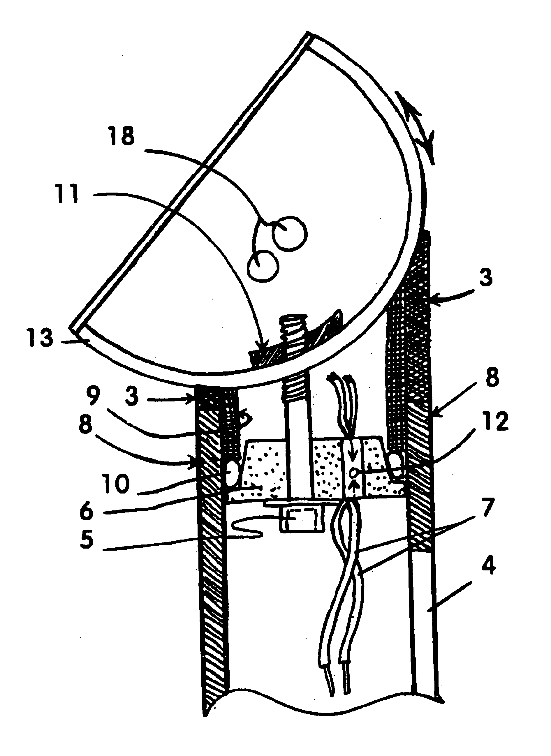
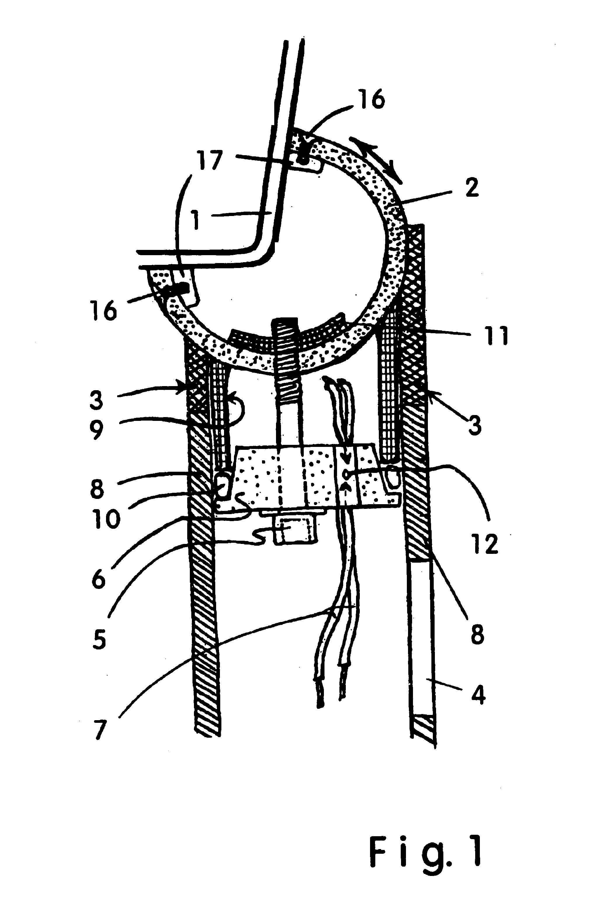
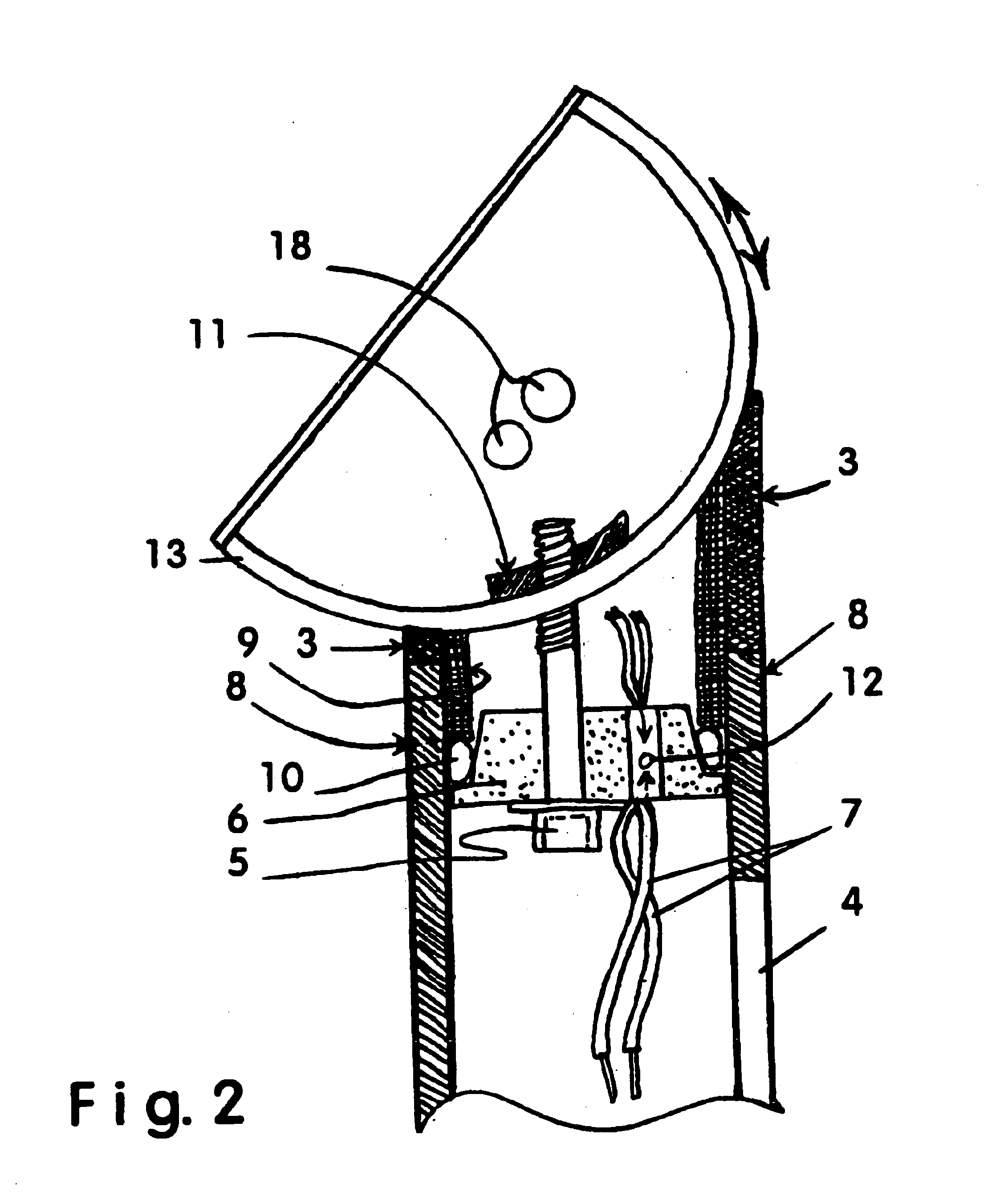
FIG. 1 and 4 show a first embodiment of the present invention having a lighting fixture body 1 mounted on an elevating member 2 that rotates in a vertical plane, elevating member 2 being cradled on a rotating member 3 that allows for rotation of lighting fixture body 1 and elevating member 2 in a horizontal plane. The size of elevating member is not critical as long as it is appropriate to the size and configuration of lighting fixture body 1 used. A vertical post or tube 8 supports rotating member 3 and has an access opening 4 positioned at a spaced-apart distance from rotating member 3 for operator access to wiring terminations without disturbing the pre-set orientation of lighting fixture body 1. FIG. 1 also shows the first embodiment of the present invention having a split expansion sleeve 9 extending respectively into the central bores of vertical post or tube 8 and rotating member 3 to hold rotating member 3 in line with vertical post or tube 8. FIG. 1 further shows the first ...


PUM


Abstract

A lighting standard, and a method for its use, that has incorporated into its top end a swivel means for the adjustment of a lighting fixture head in train and elevation. The swivel means also incorporates passages through which electrical conductors are passed to provide power for the lighting fixture. The elevating member can include a fixture body, or in the alternative, the fixture body and elevating member can be separate components. The lower end of the standard can be buried in the ground, with the wiring necessary to power the fixture entering through the lower end of the standard and wiring terminations being made through a covered opening on the side of the standard. In the alternative, the standard can be connected directly to a junction box. Applications may include, but are not limited to, landscape lighting, accent lighting, and the lighting of signs, driveways, and walkways.

Description

BACKGROUND1. Field of InventionThis invention relates to outdoor fixtures for illuminating small areas, specifically to a lighting standard, and a method for its use, that has Incorporated into its top end a swivel means for the adjustment of a lighting fixture head in train and elevation. The swivel means also incorporates passages through which electrical conductors are passed to provide power for the lighting fixture. The elevating member can include a fixture body, or in the alternative, the fixture body and elevating member can be separate components. Further, the lower end of the standard can be buried in the ground, with the wiring necessary to power the fixture entering through the lower end of the standard and wiring terminations being made through a covered opening on the side of the standard. In the alternative, the standard can be connected directly to a junction box. When combined with fluorescent lamps, the present invention provides a clean, neat, compact, aesthetical...

Claims


Application Information

Patent Timeline
IPC IPC(8): F21V21/116F21V21/10F21V21/14F21V21/30F21S8/08
CPCF21S8/081F21V21/30F21V21/116
Inventor GURITZ, MICHAEL LEE
Owner GURITZ MICHAEL LEE
Learn More