Airflow indicator

a technology of airflow and indicator, which is applied in the direction of vacuum cleaners, mechanical suction control, cleaning processes and apparatuses, etc., can solve the problems of reducing the life of motors, consumer cannot finish cleaning carpet/surface, and the thermostat is not good solution

Inactive Publication Date: 2005-01-04
ROYAL APPLIANCE MFG
View PDF30 Cites 13 Cited by
  • Summary
  • Abstract
  • Description
  • Claims
  • Application Information

AI Technical Summary

Problems solved by technology

The end result can be a reduced motor life due to increased loading.
There are several reasons that the hold-open thermostat is not a good solution.
Once the unit heats up to the trigger point, the consumer can no longer finish cleaning the carpet / surface.
The fact that the unit will shut off and remain off for a period of thirty minutes or more is a big inconvenience to the consumer and therefore a product return issue as well.
One problem with air valve springs is that they often have low spring rates and large displacements once the desired opening pressure is reached.
Larger spring rates are not feasible because a large spring rate usually translates to a system that is too sensitive to variations in assembly and manufacturing methods.
With low spring rates, there are many inherent difficulties in achieving a system that performs accurately and precisely.
In particular, the wire form spring design approach has many challenges.
Often times, variations in plastic part dimensions prevent consistent compression.
Variations in the wire form manufacture are costly to minimize and often require the use of precision springs.
Often times, the displacement of the valve is different from valve to valve, and this results in different airflow rates into the bleed valve.
Another problem with the prior art systems described above is that once the air valve opens, it is often difficult to have the valve close at a desired pressure that is different than the opening value and ideal for customer use.
It is very difficult to try to control the close value of a valve system that uses a wire form spring.

Method used


Image

  • Airflow indicator
  • Airflow indicator
  • Airflow indicator

Examples


Embodiment Construction

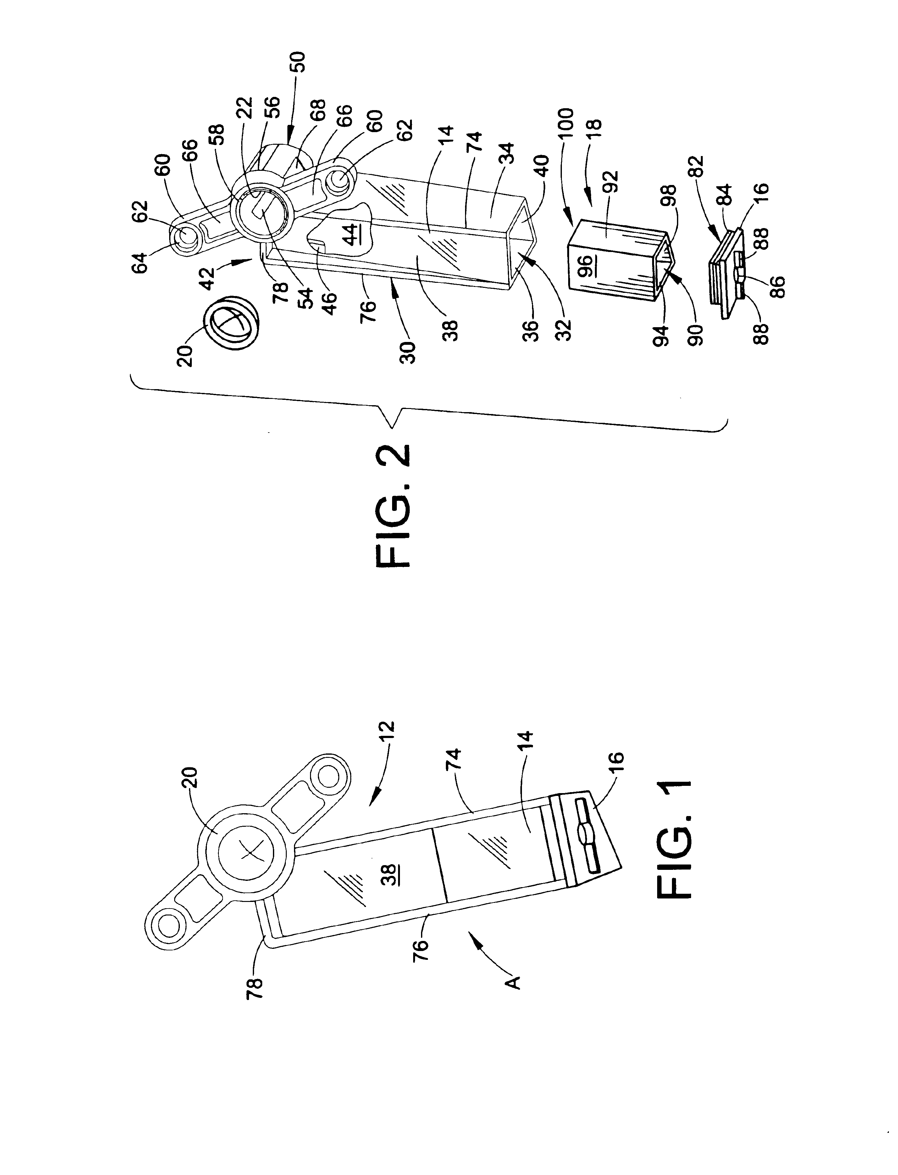
Referring now to the drawings, wherein the showings are for purposes of illustrating a preferred embodiment of this invention only and not for purposes of limiting same, FIG. 1 shows a airflow indicator A according to the preferred embodiment of the present invention.

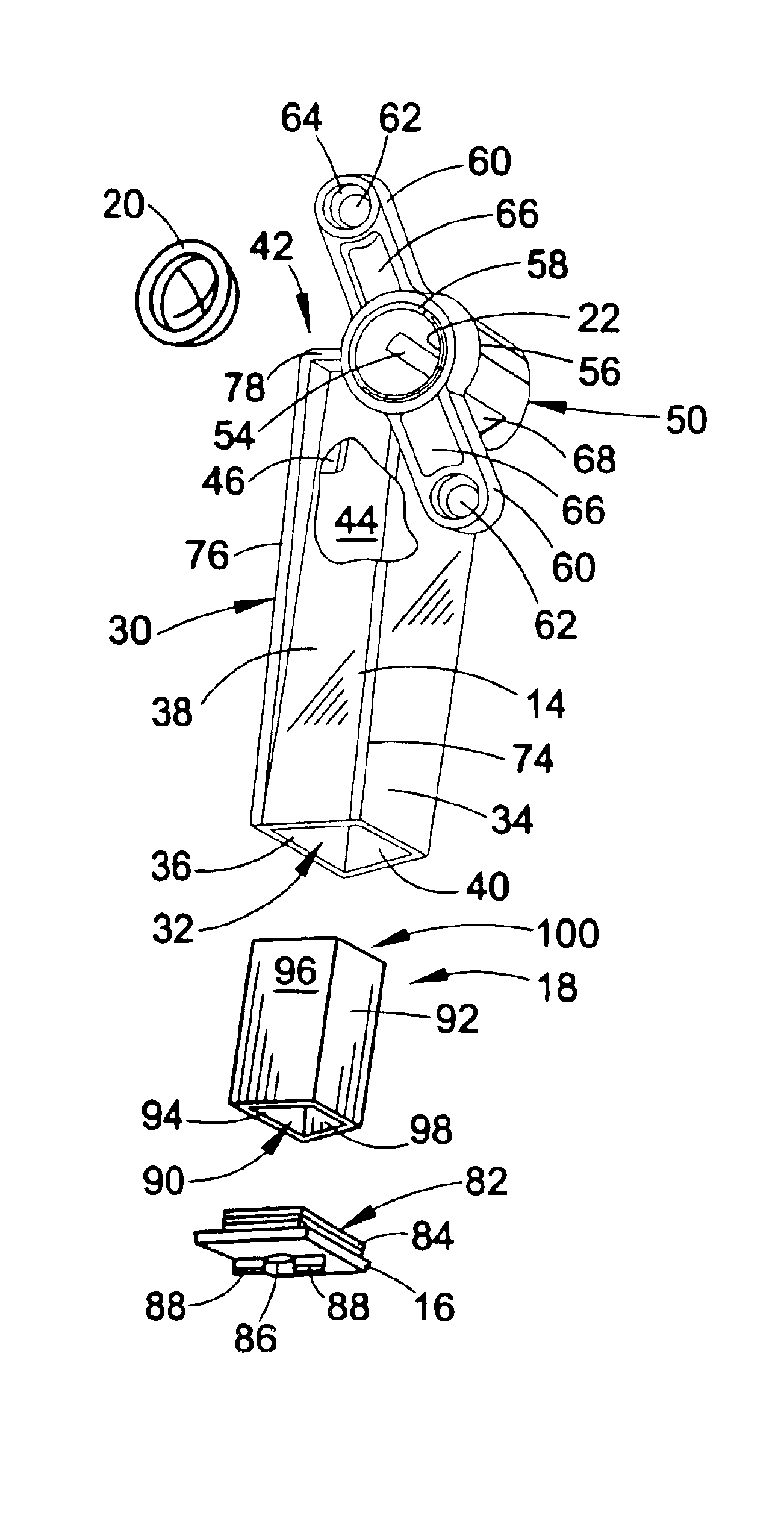
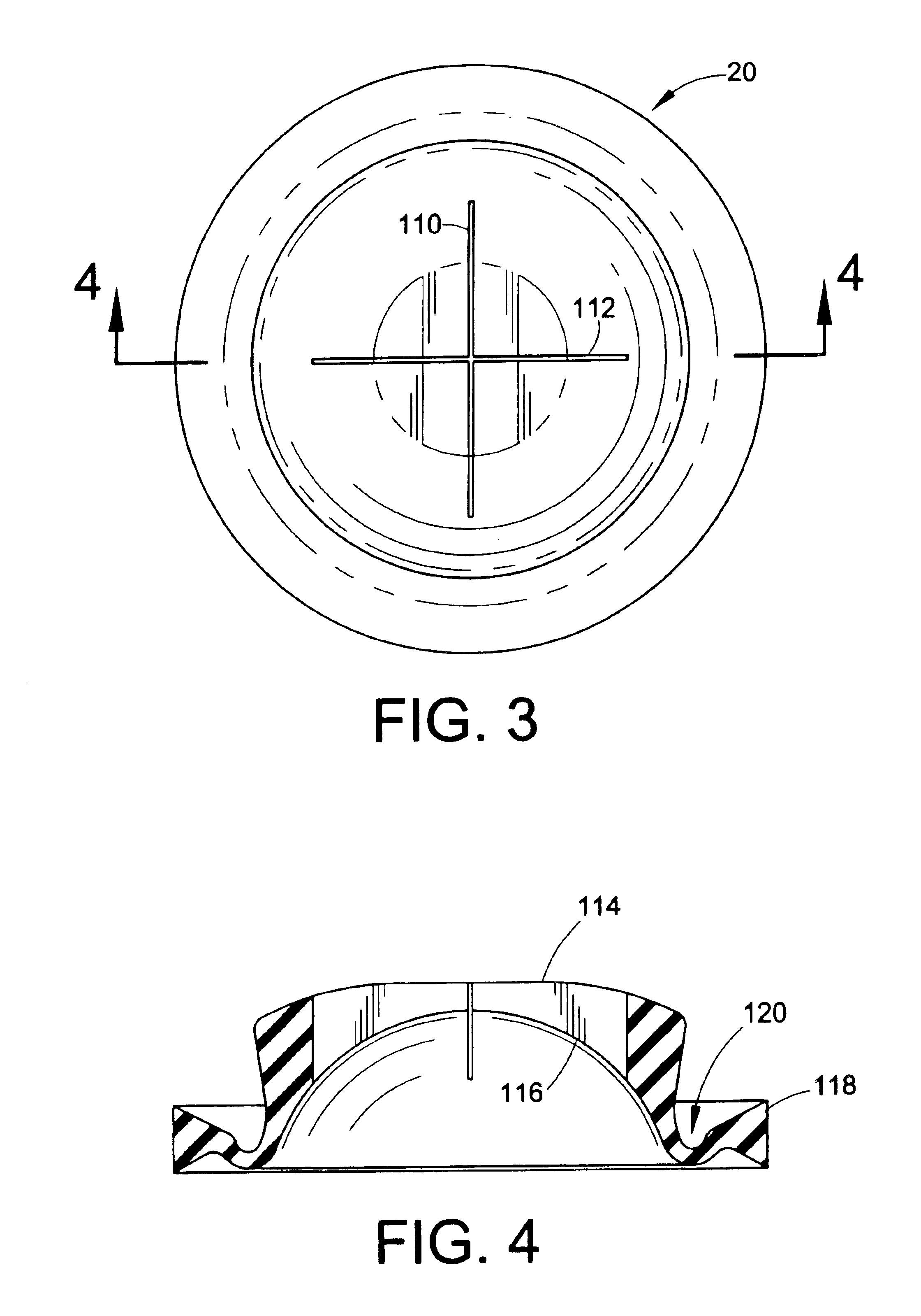
The airflow indicator A includes a housing 12 having a body 14 and a cap 16. With reference now to FIG. 2, a piston 18 is operatively received within the housing 12 as will be discussed in more detail below. A diaphragm or bleed valve 20 is mounted to the housing 12 adjacent an air outlet 22. The housing body 14, the cap 16, and the piston 18 can be fabricated from plastic material.

With continued reference to FIG. 2, the housing body 14 can comprise a generally hollow trapezoidal or prismatic portion 30 having an open end or end opening 32. The trapezoidal portion 30 is comprised of a plurality of elongated sides including parallel sides 34,36, a front side 38, and a rear side 40. Unless otherwise indicated, the terms f...


PUM


Abstract

An airflow indicator for a vacuum cleaner is provided. The airflow indicator comprises a housing mounted to a casing of the vacuum cleaner. A piston chamber is defined within the housing. A piston is received in the piston chamber and is movable therein between a first position and a second position. A first port is formed in the housing and communicates with the piston chamber. The first port is open to ambient. A second port is formed in the housing and communicates with the piston chamber. The second port is spaced from the first port and is open to the filter chamber of the vacuum cleaner. A valve is mounted to the housing for obstructing air passage into the piston chamber. The valve includes a diaphragm having a slit that opens in response to a predetermined pressure differential between the first port and the second port.

Description

BACKGROUND OF THE INVENTIONThe present invention relates to an airflow indicator. More particularly, it relates to an airflow indicator that signals when a filter chamber in a vacuum cleaner is full.Typical vacuum cleaners load a suction motor more and more as a dirt holding means such as a dirt bag, cup, container or the like becomes full. Many vacuum systems use the airflow through the system to cool the motor (particularly in clean air type vacuums). As the dirt holding means of the vacuum becomes more and more full, there is less and less cooling air passing through the motor. The end result can be a reduced motor life due to increased loading.One attempt at remedying this problem is the use of a hold-open thermostat device which shuts the unit off when the system airflow is not adequate to cool the motor. The hold-open thermostat device then prevents the motor from driving a brush roll of the vacuum cleaner until the motor has cooled down, such as for a period of thirty minutes...

Claims


Application Information

Patent Timeline
Patent Type & Authority Patents(United States)
IPC IPC(8): A47L9/19A47L9/10A47L9/00
CPCA47L9/19A47L9/0072
Inventor THUR, CHARLES J.CIPOLLA, MARK E.BARBECK, CRAIGPALIOBEIS, STEVEN J.
Owner ROYAL APPLIANCE MFG
Why Eureka
Try Eureka