Ported pressure relief valve

a pressure relief valve and port technology, applied in the field of valves, can solve the problems of increasing the number of components required, affecting the operation of the valve, so as to improve the fuel and pressure control, and reduce the “ramp up” time

Inactive Publication Date: 2005-01-04
CARTER FUEL SYST
View PDF9 Cites 22 Cited by
  • Summary
  • Abstract
  • Description
  • Claims
  • Application Information

AI Technical Summary

Benefits of technology

The ported pressure relief valve of the present invention eliminates the need for a check valve commonly found in the outlet of many fuel pumps. In systems where fuel pump operation is controlled either externally, for example, by the engin...

Problems solved by technology

On the other hand, too much pressure can build up in the fuel system.
If an over pressure condition is not prevented, seals, fuel line connections, etc., may be compromised as is the subsequent fuel del...

Method used


Image

  • Ported pressure relief valve
  • Ported pressure relief valve

Examples


Embodiment Construction

The following detailed description illustrates the invention by way of example and not by way of limitation. This description will clearly enable one skilled in the art to make and use the invention, and describes several embodiments, adaptations, variations, alternatives and uses of the invention, including what I presently believe is the best mode of carrying out the invention. As various changes could be made in the above constructions without departing from the scope of the invention, it is intended that all matter contained in the above description or shown in the accompanying drawings shall be interpreted as illustrative and not in a limiting sense.

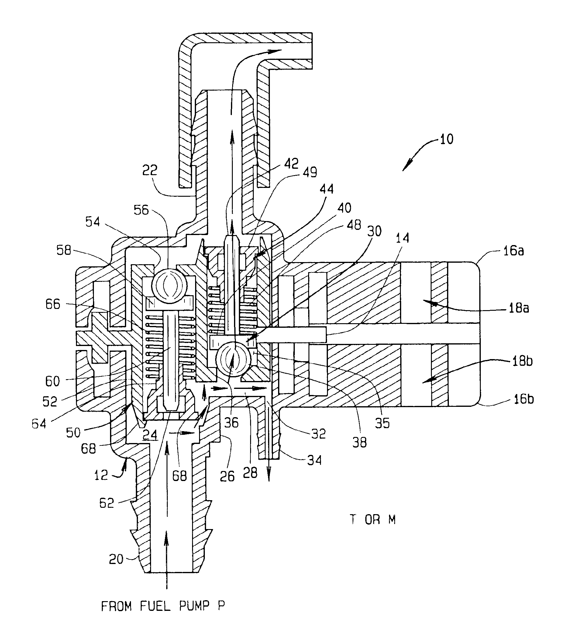
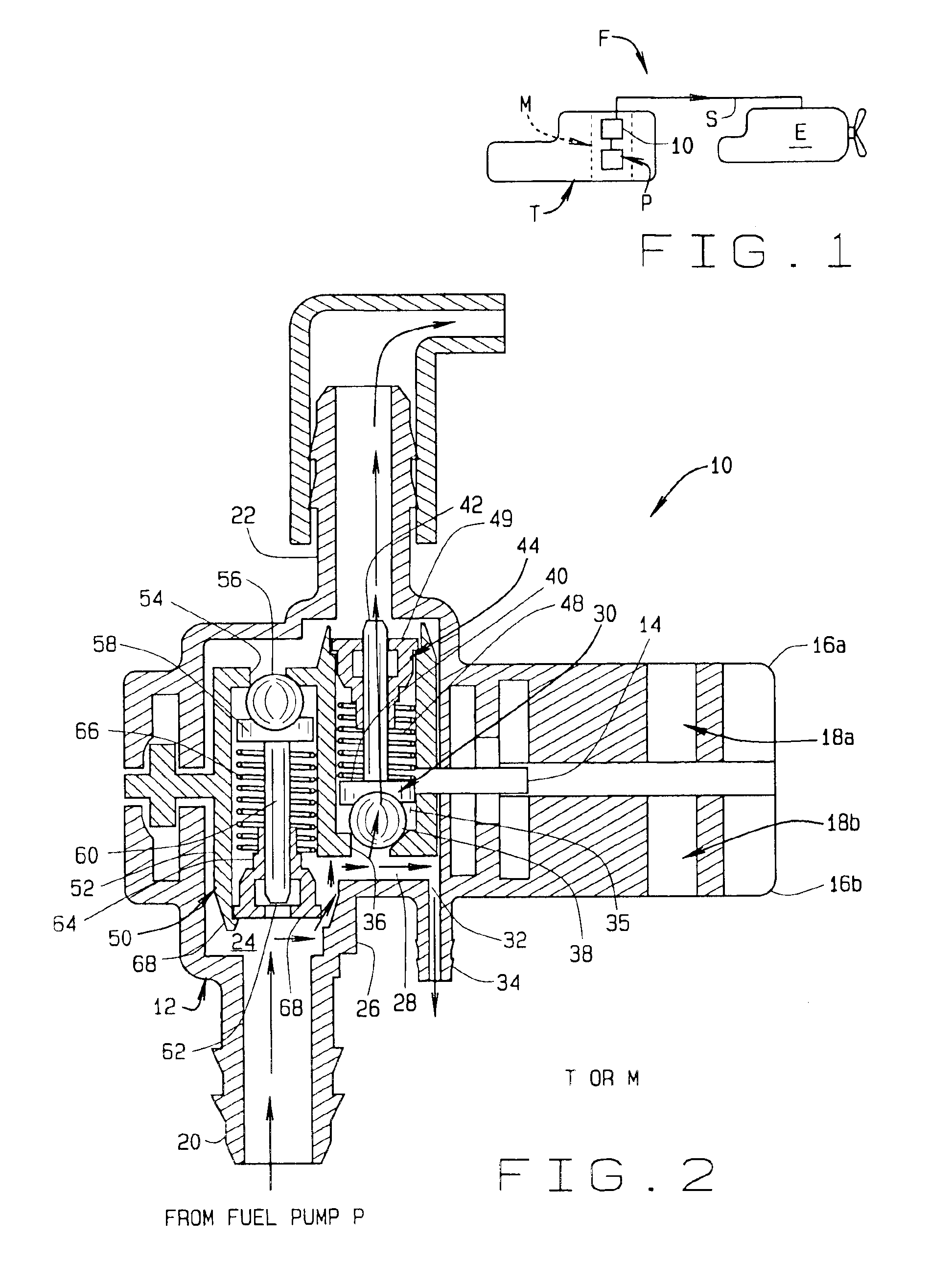
Referring to FIG. 1, a fuel system F for an internal combustion engine E includes a source of fuel such as a fuel tank T. In many current automotive vehicles, a fuel module M is installed in the fuel tank with fuel being drawn from the tank into the module and then pumped from the module to the engine. A fuel pump P draws fuel from ...


PUM


Abstract

A ported pressure relief valve (10) used in an automotive fuel system (F) includes an unrestricted constant bleed orifice (32) for routing pressurized fuel from a fuel pump (P) back to a fuel source (T, M) when an engine (E) is running. A check valve (30) prevents flow from a fuel system back to the fuel source when the engine is off, so to retain sufficient pressure in the delivery system that the engine will readily start when cranked. A pressure relief valve (50) drains fuel from the delivery system back to the source of fuel in response to a pressure build up in the fuel delivery system above a predetermined pressure level so to prevent an overpressure condition which would otherwise damage the fuel delivery system.

Description

CROSS REFERENCE TO RELATED APPLICATIONSNoneSTATEMENT REGARDING FEDERALLY SPONSORED RESEARCH OR DEVELOPMENTN / ABACKGROUND OF THE INVENTIONThis invention relates to valves used in automotive fuel systems in combination, for example, with a fuel pump, and more particularly, to a ported pressure relief valve (PPRV) mounted in the fuel path between the pump and fuel rail (for fuel injected engines) or a carburetor to provide a constant vapor purge when the engine is running, and to provide a means of allowing vapor to escape when the engine is off.In conventional fuel systems, fuel is drawn from a fuel tank or reservoir into a low pressure inlet of an electric fuel pump. High pressure fuel from an outlet of the fuel pump is then delivered to the engine through a fuel rail. In some systems, unused fuel is directed back to the tank or reservoir through a return portion of the rail. Also in some systems, excess fuel flow is used to power a jet pump which is used to fill a reservoir in the fu...

Claims


Application Information

Patent Timeline
IPC IPC(8): F02M37/00F02M63/00F02M69/54F16K17/04
CPCF02M37/0029F16K17/0406F02M69/54F02M63/0043F02M37/0052F02M2200/44
Inventor YORK, GEORGEMEYER, PAULWALSH, MARTIN
Owner CARTER FUEL SYST
Why Eureka
Try Eureka