Laryngoscope with image sensor

a technology of image sensor and laryngoscope, which is applied in the field of medical devices, can solve the problems of inability to monitor the laryngoscope, the airway passage center of the airway, and the damage of the airway by medical professionals

Inactive Publication Date: 2005-01-11
NUVISTA TECH CORP
View PDF135 Cites 53 Cited by
  • Summary
  • Abstract
  • Description
  • Claims
  • Application Information

AI Technical Summary

Benefits of technology

In one embodiment, the present invention includes a laryngoscope integrated with an imaging device such as a camera. The laryngoscope of this embodiment includes a blade for insertion into the patient's airway passage. This blade can be permanently affixed to a handle or can be removably mounted so that different blades can be connected to the handle. On one side of the blade—generally the left side—is a flange that sits perpendicular to the blade. The blade secures the patient's tongue to one side of the mouth and provides a surface for the endotracheal tube to engage as it is inserted into the airway. For proper perspective, the laryngoscope should be viewed with the handle up, the blade down and away.

Problems solved by technology

Even with the use of a laryngoscope, medical professionals often damage a patient's airway passage when inserting the endotracheal tube.
The reasons that medical professionals damage the airway passage center is their inability to monitor the laryngoscope and endotracheal tube as it is being inserted.
These laryngoscopes, however, are not completely satisfactory.
Although the laryngoscope with the integrated camera system contains some improvements over the basic laryngoscope, these systems are not always satisfactory.
Unfortunately, when the camera's view is blocked, the health care professional is “blind” and prone to damaging the patient's airway passage.

Method used


Image

  • Laryngoscope with image sensor
  • Laryngoscope with image sensor
  • Laryngoscope with image sensor

Examples


Embodiment Construction

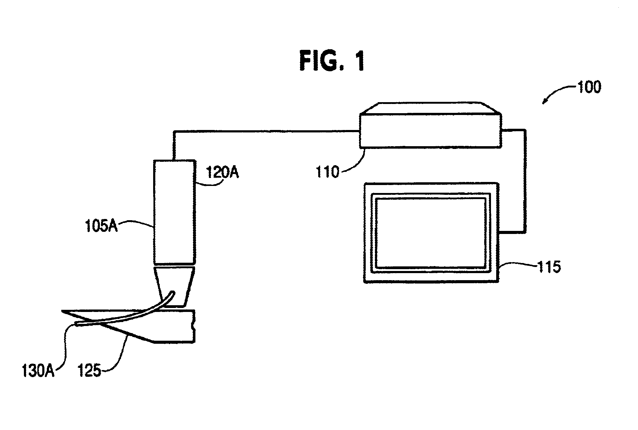
Referring to FIG. 1, it illustrates a system 100 constructed in accordance with one embodiment of the present invention. In this embodiment, an optically-enabled laryngoscope 105A is connected to a camera controller 110 and a remote viewing device 115 such as a TV or video monitor. In operation, the medical professional grasps the handle 120A of the laryngoscope 105A and inserts the blade portion 125 into the patient's airway passage. The camera 130A that is fixed to the blade 125 can then capture an image of the airway passage and transmit that image to the camera controller 110 for display at the remote viewing device 115. The medical professional can then use the displayed image to guide an endotracheal tube into the patient's airway passage.

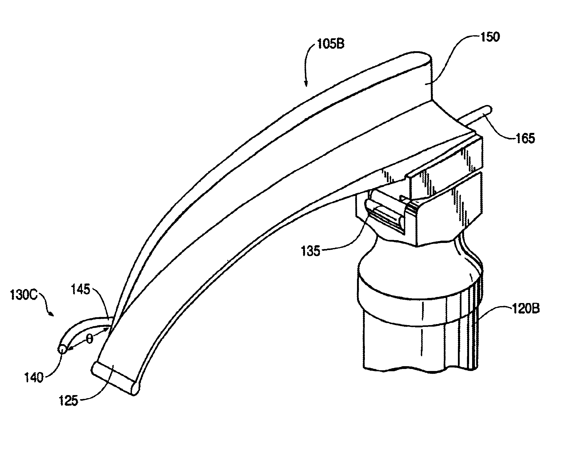
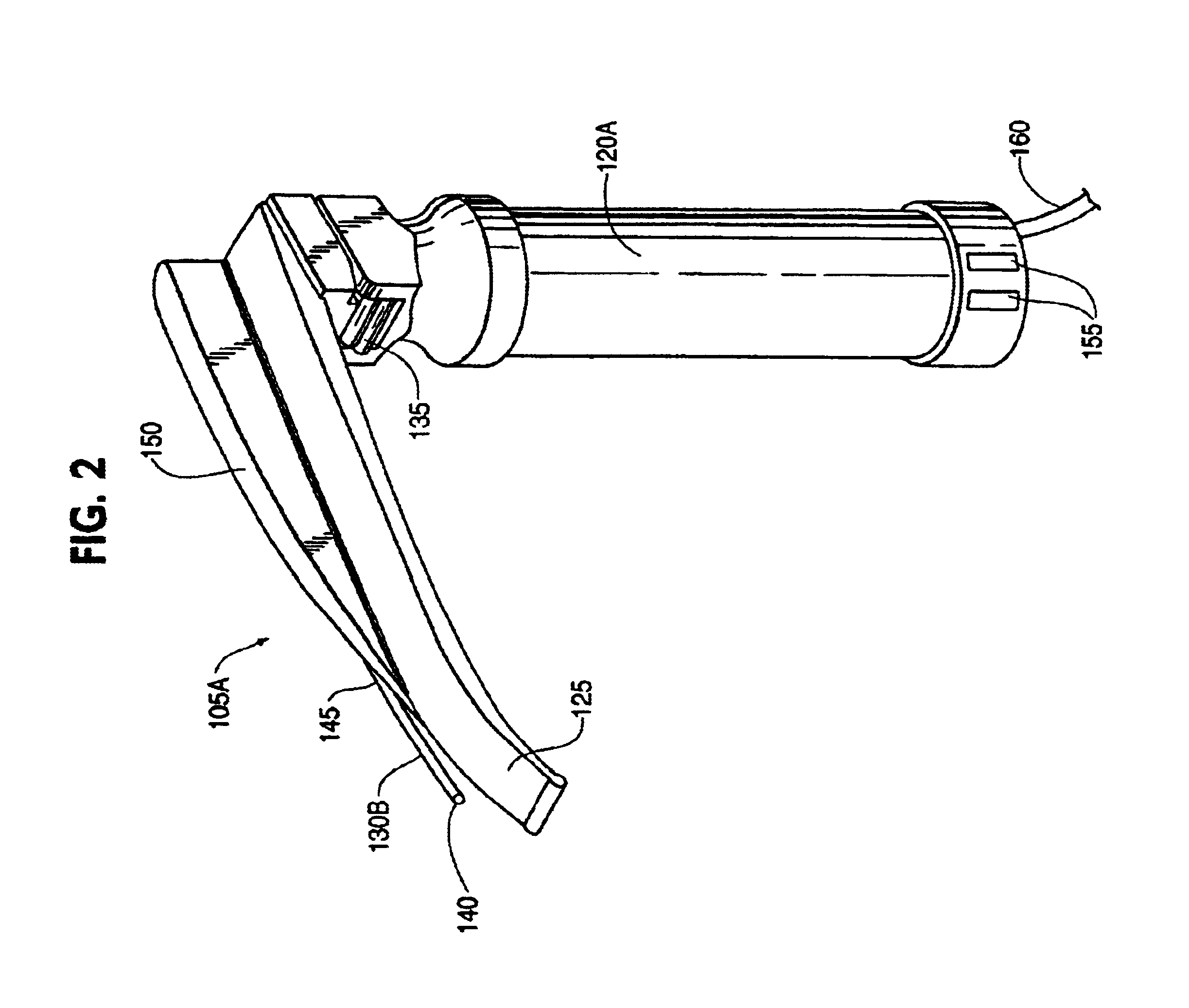
Referring now to FIG. 2, it illustrates one embodiment of a laryngoscope 105A in accordance with the principles of the present invention. In this embodiment, a removable blade 125 is attached to a handle 120A by the coupler 135, which provide...


PUM


Abstract

A laryngoscope and viewing system configured to provide imaging of a patient's airway passage during intubation is described. In one embodiment, the described device includes a handle; a blade attached to the handle, a flange attached to one side of the blade; a transmission cable connected to the opposite side of the blade; and a camera connected to the transmission cable, wherein the camera is offset from the blade in at least one of the X plane and the Y plane.

Description

FIELD OF THE INVENTIONThe present invention relates generally to medical devices. In particular, but without limitation, the present invention relates to a laryngoscope and viewing system configured to provide imaging of a patient's airway passage during intubation and similar medical procedures.BACKGROUND OF THE INVENTIONIn a process known as “intubation,” an endotracheal tube is inserted into a patient's airway passage to facilitate breathing during certain medical procedures. To avoid damaging the airway passage while inserting the endotracheal tube, medical professionals generally use a laryngoscope to open and view the airway passage and to secure the patient's tongue to one side of the mouth. A typical laryngoscope includes a rigid, curved structure with a smooth tip that engages the tissue of the patient's tongue and airway passage. Laryngoscopes often also include a guide surface for directing the endotracheal tube as it is inserted into the airway passage.Even with the use ...

Claims


Application Information

Patent Timeline
Patent Type & Authority Patents(United States)
IPC IPC(8): A61B1/267
CPCA61B1/267
Inventor MAZZEI, WILLIAM J.DAVIDSON, TERENCE M.RICHIERI, STEVEN P.
Owner NUVISTA TECH CORP
Why Eureka
Try Eureka