Integrated compressor drier apparatus

a compressor and compressor technology, applied in the direction of machines/engines, liquid fuel engines, separation processes, etc., can solve the problems of expensive and complicated dryers

Inactive Publication Date: 2005-01-18
SULLAIR CORP
View PDF23 Cites 43 Cited by
  • Summary
  • Abstract
  • Description
  • Claims
  • Application Information

AI Technical Summary

Problems solved by technology

Such moisture free pressurized gas or air is normally achieved by using various forms of gas or air drying equipment including refrigeration driers, however, such driers are expensive and complicated.

Method used


Image

  • Integrated compressor drier apparatus
  • Integrated compressor drier apparatus
  • Integrated compressor drier apparatus

Examples


Embodiment Construction

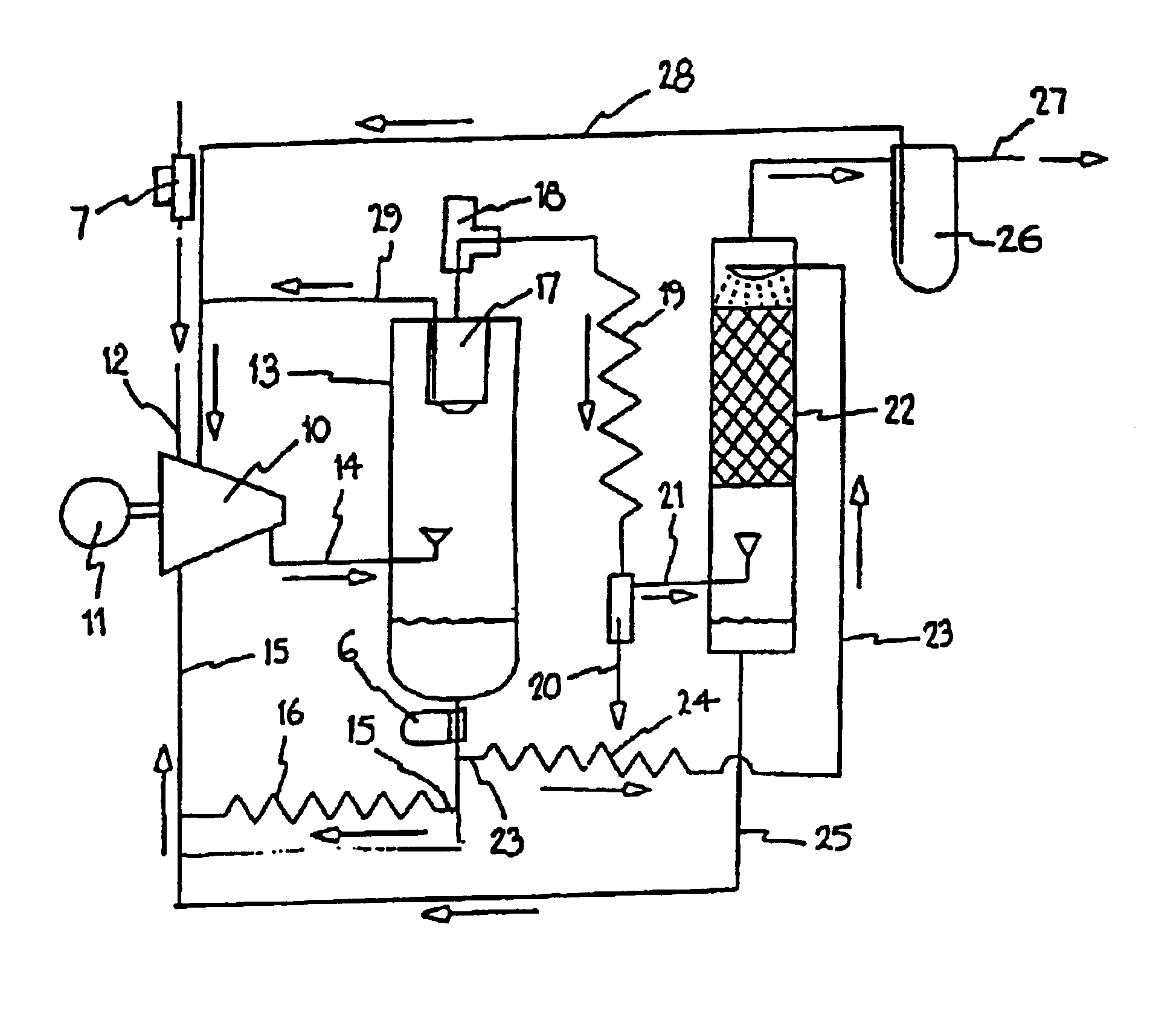
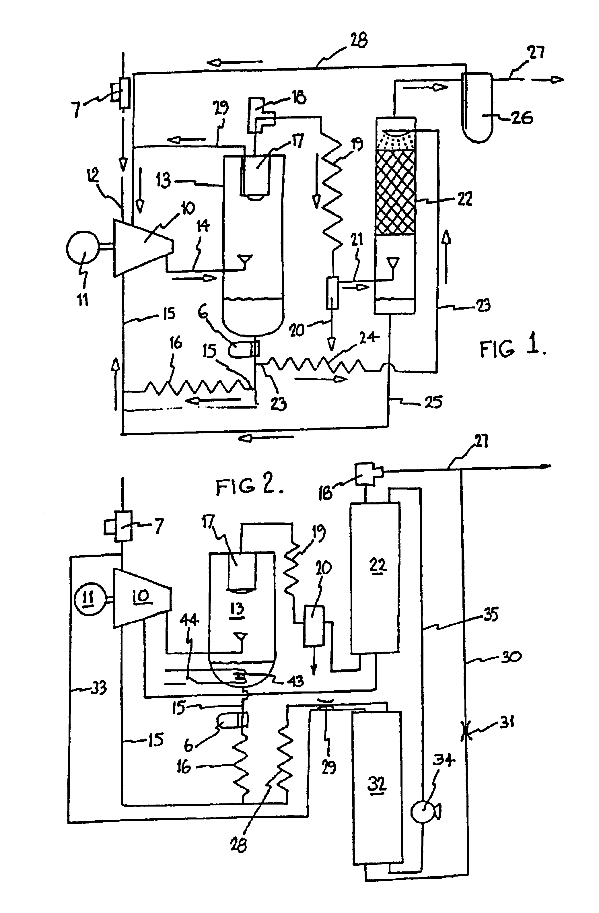
As illustrated in FIG. 1, a compressor system according to this preferred embodiment of the present invention may include a compressor unit 10 driven by a motor 11 which receives a gas (typically air) to be compressed at 12 via an inlet valve 7. The rotary compressor unit 10 may be a screw compressor of any known configuration or in fact any other form of rotary compressor. The system further includes a separator vessel 13 receiving compressed gas and entrained liquid via line 14 with a preliminary separation of gas and liquid occurring therein. The liquid is collected in a lower region of the vessel 13 and returned via line 15, a liquid or lubricant filter 6, and a liquid cooler 16, to a lower pressure region of the compressor unit 10. Compressed gas leaves the vessel 13 via a preliminary filter means 17 and a minimum pressure valve 18. The compressor system thus described is essentially conventional in nature and within the context of this invention might be substituted by any oth...


PUM

PropertyMeasurementUnit
temperatureaaaaaaaaaa
pressureaaaaaaaaaa

Abstract

A rotary compressor system having a drive rotary compressor unit, a separator vessel (13) receiving compressed gas and entrained liquid from said compressor for collecting the liquid therein and for returning the liquid to a lower pressure zone of the compressor and a moisture absorber receiving compressed gas flow leaving a separation zone of the separator vessel and passing the compressed gas flow relative to a flow of said liquid such that moisture in the compressed gas flow is transferred to said liquid.

Description

BACKGROUND OF THE INVENTION1) Field of the InventionThe present invention relates to improvements in rotary compressor systems particularly adapted to provide clean dry compressed gas at a discharge point therefrom.2) Description of Related ArtThere is increasingly a need to provide moisture free pressurized gas or air. Such moisture free pressurized gas or air is normally achieved by using various forms of gas or air drying equipment including refrigeration driers, however, such driers are expensive and complicated. The objective therefore is to provide in a simplified and inexpensive way, a rotary compressor system capable of providing clean dry compressed gas.BRIEF SUMMARY OF THE INVENTIONAccordingly, the present invention provides a rotary compressor system utilising a liquid therein, said rotary compressor system including a driven rotary compressor unit adapted to receive gas to be compressed, a separator vessel arranged to receive compressed gas and entrained liquid from said...

Claims


Application Information

Patent Timeline
Patent Type & Authority Patents(United States)
IPC IPC(8): B01D53/18B01D53/26F04C29/04F04C29/00F04C18/16F04C29/12F04C18/356F04C29/02
CPCB01D53/18B01D53/263F04C29/0092F04C29/042Y10S55/17F04C18/16
Inventor KITCHENER, ANTHONY JOHN
Owner SULLAIR CORP
Why Eureka
Try Eureka