Pipe-gripping structure having load rings

a technology of load ring and pipe gripping, which is applied in the direction of mechanical equipment, transportation and packaging, and wellbore/well accessories, etc., can solve the problems of deformation or failure of the bottom toe area of the slip segment, damage to the load supporting device may require replacement of the entire slip segment, and damage to the load supporting devi

Inactive Publication Date: 2005-01-25
VARCO I P INC
View PDF47 Cites 63 Cited by
  • Summary
  • Abstract
  • Description
  • Claims
  • Application Information

AI Technical Summary

Problems solved by technology

These high stress concentrations often result in deformation or failure of the bottom toe area of the slip segments.
Although these permanent load supporting devices may improve the performance of the slip, damage to the load supporting devices may require replacement of the entire slip segment.
Damage to these load supporting devices may occur due to a variety of reasons.
For example, if a slip is used to hold a drilling string large enough to create axial loads close to the slip's rate

Method used


Image

  • Pipe-gripping structure having load rings
  • Pipe-gripping structure having load rings
  • Pipe-gripping structure having load rings

Examples


Embodiment Construction

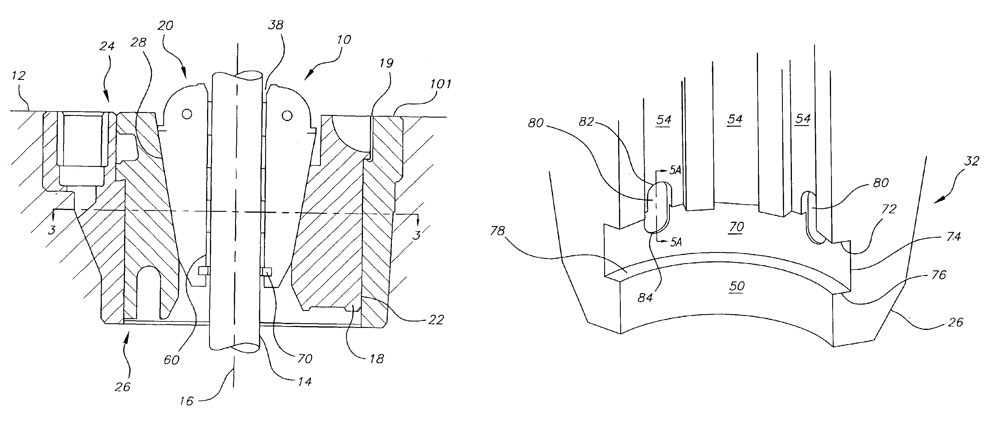
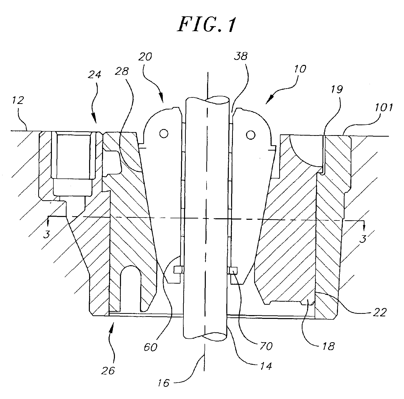
FIG. 1 illustrates a conventional rotary table 12 for suspending a pipe or drill string 14 directly above a well bore and for rotating the drill string about a vertical axis 16. The table 12 includes a manual slip system 10 according to the present invention. The system includes a slip bowl 18, which is mounted within a central opening 19 of the master bushing 101 and a rotary slip assembly 20, which is rotatably disposed within the slip bowl 18. The slip bowl 18 is defined by a cylindrical outer wall 22 that extends axially between an upper “head” region 24 and a lower “toe” region 26, and a tapered inner wall 28 having a reduced diameter at the toe region.

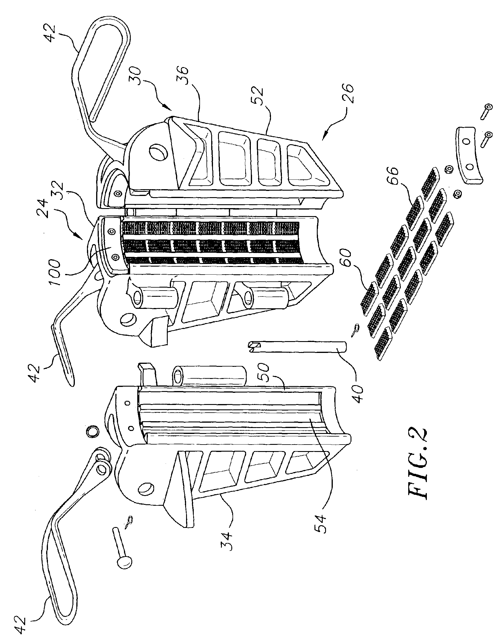
The slip assembly 20 generally comprises a plurality of slip segments having tapered outer walls that are adapted to engage the tapered inner wall 28 of the bowl 18 to retain the slip assembly 20 from lateral, but not rotational movement within the bowl 18. Each slip segment carries along its inner surface a series of inserts 60 ...


PUM


Abstract

A rotary slip for supporting a drill string having a plurality of slip segments connected to define an opening for insertion of the drill string, wherein each slip segment comprises a head region, a toe region, and an inner radial surface axially extending between the head and toe regions, and wherein the inner radial surface of each slip segment comprises a circumferential groove. A plurality of axially aligned drill string gripping inserts are attached to each slip segment between the head region and the circumferential groove, wherein each insert comprises a gripping surface for contacting the drill string. A load ring is disposed within the circumferential groove of each slip element, the load ring comprising at least one securing element which is engaged by one of the plurality of axially aligned inserts to secure the load ring within the circumferential groove.

Description

FIELD OF THE INVENTIONThis invention relates to an improved pipe-gripping structure and method of manufacturing a pipe-gripping structure, and more particularly, to a method of installing load rings within a slip assembly to provide a pipe-gripping structure having improved load lift properties.BACKGROUNDIn the oilfield, when drilling for oil or gas, a platform is used to support a circular rotary table. Rotational energy is supplied to the rotary table through motors or the like, moving the rotary table in a circular fashion. The rotary table comprises a central kelly bushing which provides a central opening or bore through which a drill string passes. The kelly bushing typically provides four “pin holes” receptive of pins on a master bushing which when interlocked with the kelly bushing, drive a kelly held therein. The rotary table, kelly, master bushing and kelly bushing are art terms referring to the various parts of the drilling rig which actually impart the needed rotational f...

Claims


Application Information

Patent Timeline
IPC IPC(8): E21B19/10E21B19/00F16B2/06
CPCE21B19/10Y10S294/902
Inventor MASON, DAVIDDE PONT, ALBERTVAN RIJZINGEN, HANSKRIJNEN, ANTONDE LAAT, CORNELIS
Owner VARCO I P INC
Why Eureka
Try Eureka