Connector housing with resilient lock having increased rigidity

Inactive Publication Date: 2005-02-08
SUMITOMO WIRING SYST LTD
View PDF2 Cites 10 Cited by
  • Summary
  • Abstract
  • Description
  • Claims
  • Application Information

AI Technical Summary

Benefits of technology

The locks and the deformation preventing portions overlap along the thickness direction, which is the deformation direction of the lock. Thus, the connector can be made smaller by this overlapping thickness. Further, parts of the deformation permitting spaces corresponding to the thin portions of the lock have a large height. Therefore, the thickness of the deformation preventing portions that contact the thin portions of the lock are larger, and a sufficient strength can also be secured for the deformation preventing portions.
Deformation permitting spaces for the thick portions preferably are defined by partially cutting portions of partition walls between the cavities corresponding to th

Problems solved by technology

However, the rigidity and strength of the locks is reduced by thinni

Method used


Image

  • Connector housing with resilient lock having increased rigidity
  • Connector housing with resilient lock having increased rigidity
  • Connector housing with resilient lock having increased rigidity

Examples


Embodiment Construction

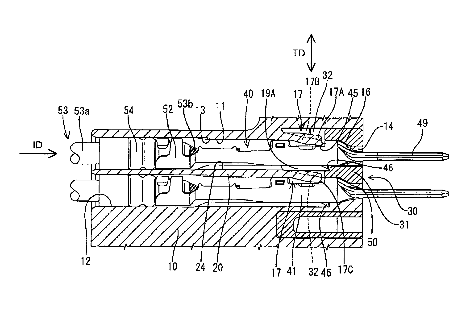
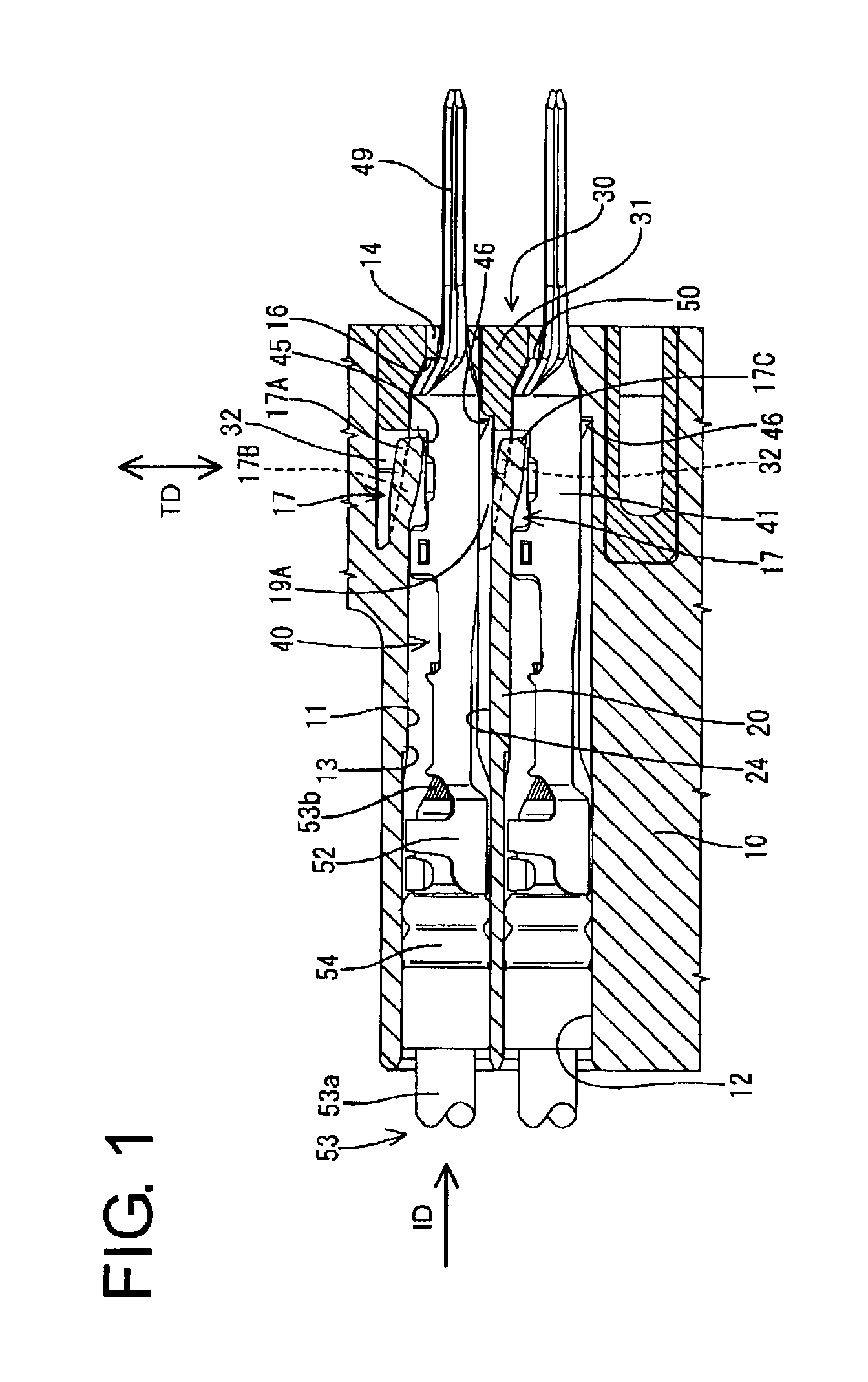
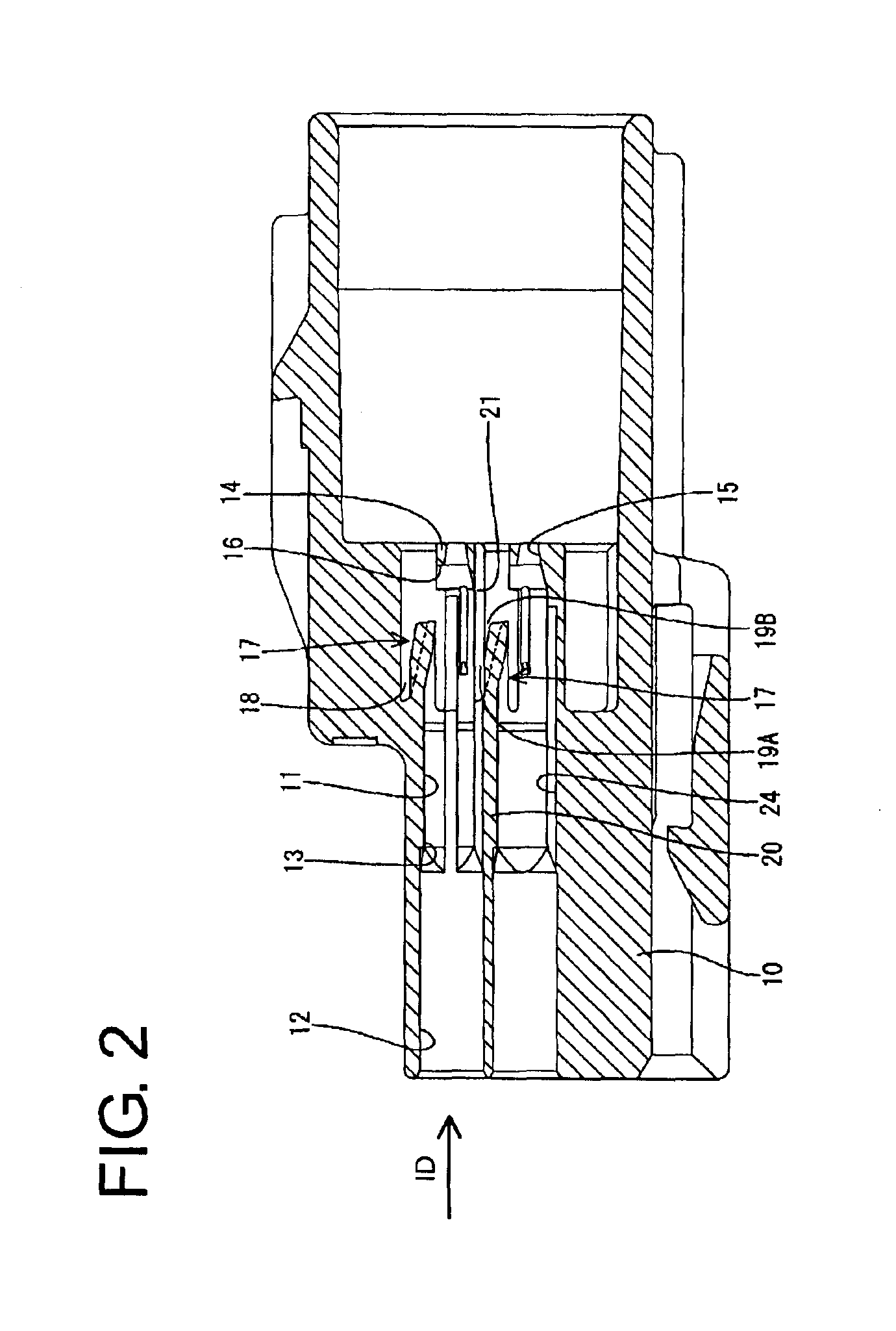
A connector according to the invention has a housing identified by the numeral 10 in FIGS. 1 to 10. The housing 10 is formed e.g. of a synthetic resin and has cavities 11 that open at opposite front and rear ends of the housing 10. The cavities 11 are arranged substantially side by side at upper and lower stages. A substantially round sealing surface 12 is defined on the inner periphery of the rear end of each cavity 11. A portion of each cavity 11 before the sealing surface 12 has a substantially rectangular cross section, and a step-shaped receiving portion 13 is formed on the ceiling before the sealing surface 12. The receiving portion 13 is more backward than the longitudinal center of the cavity 11.

A front wall 14 stands up from the front end of the bottom wall of the cavity 11 and has an opening 15 for receiving a tab of a male terminal fitting. A substantially flat receiving surface 16 projects from the rear of the front wall 14 above the opening 15 and is aligned substantial...


PUM


Abstract

A connector has a housing (10) with cavities (11) and a lock (17) in each cavity (11) for locking a terminal fitting (40). Each lock (17) has thin portions (17B) formed by partially cutting a surface thereof facing a deformation permitting space and a thick portion (17A) thicker than the thinner portions (17B). Deformation-preventing portions (32) are insertable into recesses formed by a difference in the thickness between the thick and thin portions (17A, 17B) to restrict resilient deformation of the locks (17). The connector can be made smaller because the locks (17) and the deformation-preventing portions (32) overlap along the thickness direction.

Description

BACKGROUND OF THE INVENTION1. Field of the InventionThe invention relates to a connector with a front retainer.2. Description of the Related ArtJapanese Unexamined Patent Publication No. 5-23441 discloses a connector with a housing and with cavities that extend through the housing in a front to rear direction. Locks are cantilevered forwardly in the housing and extend along inner wall surfaces of the cavities. Deformation permitting spaces are formed in the housing adjacent the locks for permitting resilient deformation of the locks. Terminal fittings are inserted into the cavities from behind and are locked by the corresponding locks. A front retainer is mounted to a front end of the housing and has deformation preventing portions that enter the deformation permitting spaces of the housing to prevent the locks from being deformed away from the terminal fittings. As a result the terminal fittings are locked doubly and are prevented from coming out.The above-described connector requi...

Claims


Application Information

Patent Timeline
IPC IPC(8): H01R13/422H01R13/436H01R13/42
CPCH01R13/4223H01R13/4364
Inventor TSUJI, TAKESHI
Owner SUMITOMO WIRING SYST LTD
Why Eureka
Try Eureka