High-density connector assembly with improved mating capability

Inactive Publication Date: 2005-02-08
MOLEX INC
View PDF24 Cites 110 Cited by
  • Summary
  • Abstract
  • Description
  • Claims
  • Application Information

AI Technical Summary

Benefits of technology

The first and second sets of signal and ground terminals have flat blade portions that are arranged within each connector component so that the first and second sets of ground terminals preferably abut each other and extend in a vertical line down the center of the wafer. The first and second sets of signal terminals lie on opposite sides of, or “flank”, the first and second sets of ground terminals and the insulative coverings of the first and second signal terminal sets prevent unintended shorting from occurring between the signal and ground terminals. The first and second sets of signal terminals are further arranged so that one pair of first signal terminals and one pair of second signal terminals are disposed on opposite sides of one of the contact portions of the first and second sets of ground terminals. In this arrangement, the L-shaped signal terminal contact portions extend in d

Problems solved by technology

In instances where the device system requires the use of multiple pairs of connectors to join the two circuit boards together, problems may occur when one or more of the connectors are misaligned.
These connectors are not able to move, or “flex” either up or down, side to side or in other directions, which can lead to serious system complications in that misalignment renders

Method used


Image

  • High-density connector assembly with improved mating capability
  • High-density connector assembly with improved mating capability
  • High-density connector assembly with improved mating capability

Examples


Example

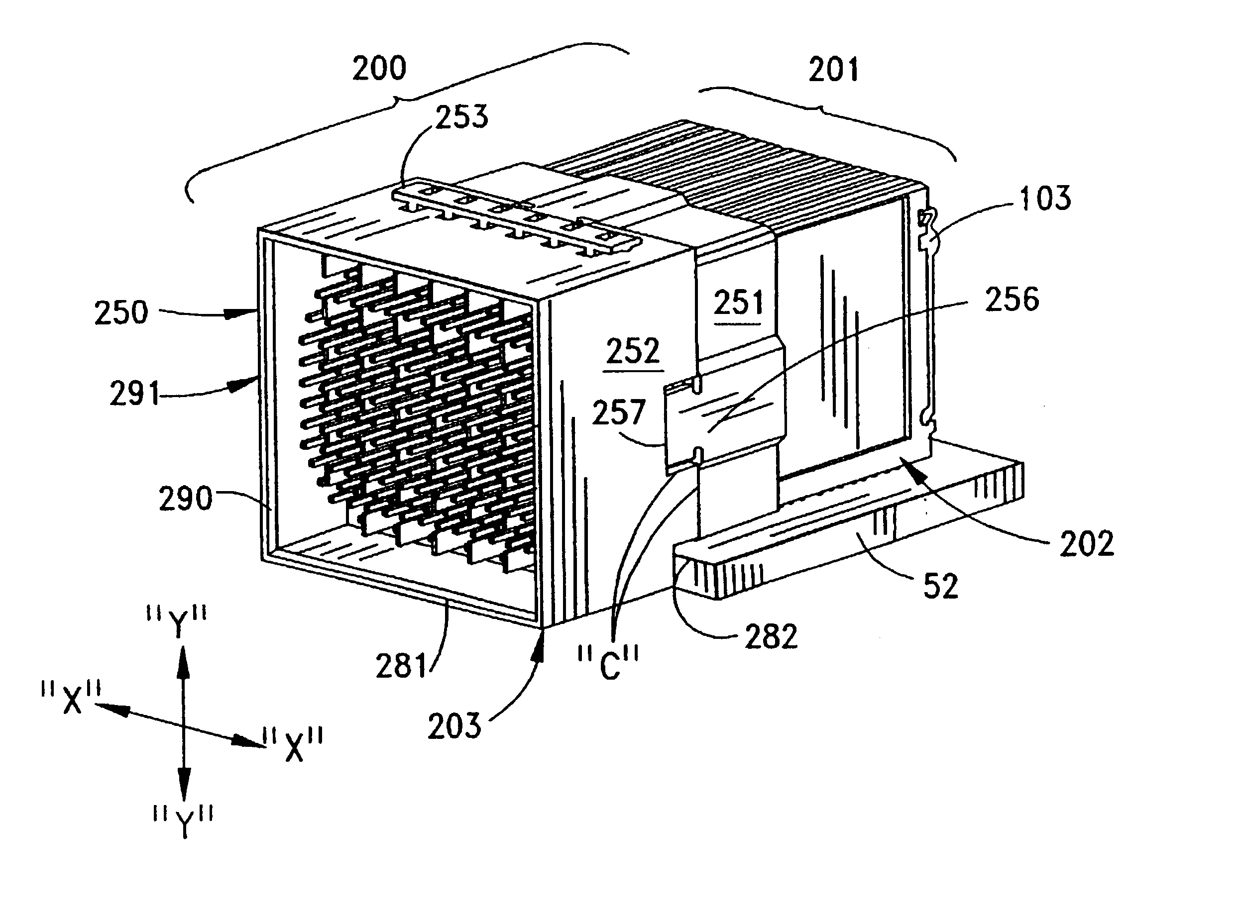
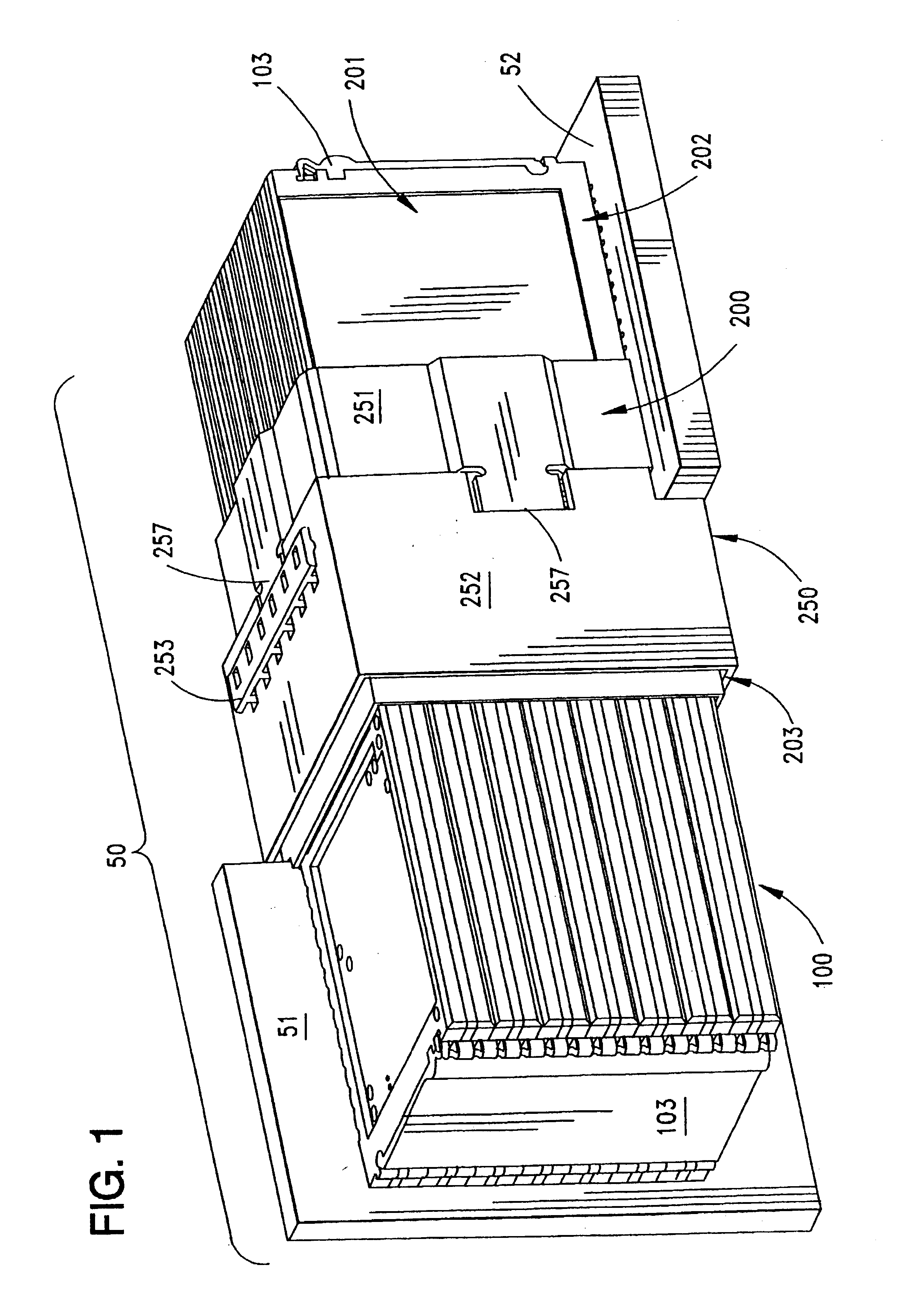
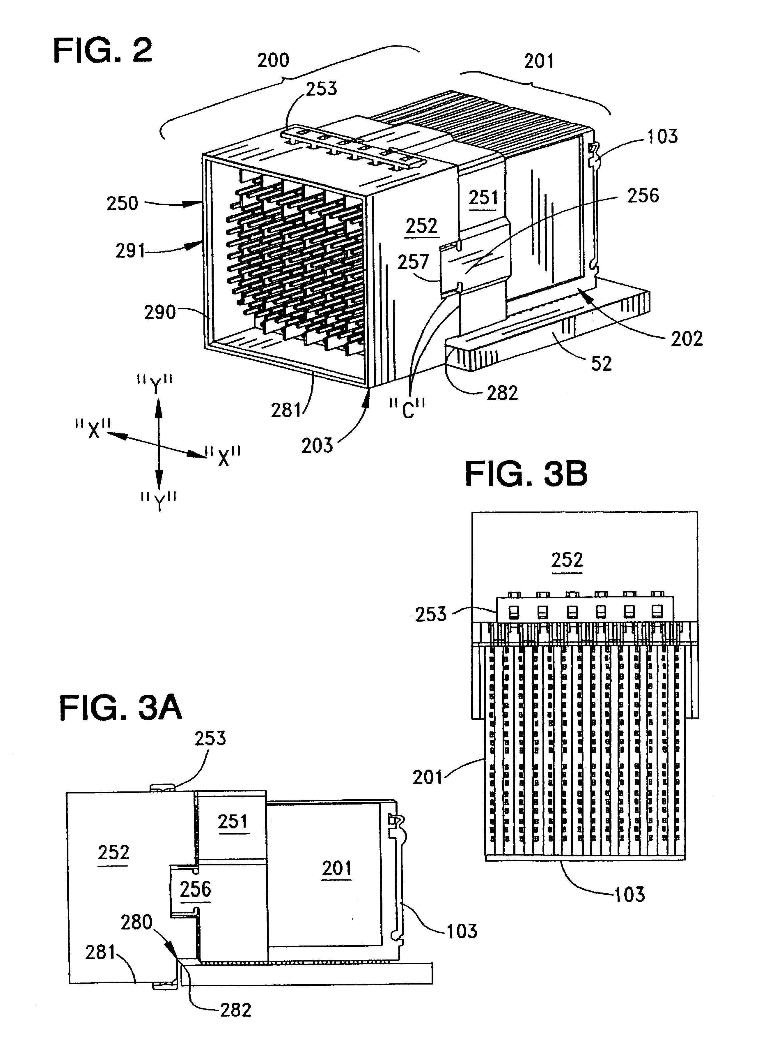
FIG. 1 illustrates a connector assembly 50 constructed in accordance with the principles of the present invention which is primarily useful in connecting two circuit boards 51, 52 together. As shown, the circuit boards 51, 52 are oriented in an orthogonal orientation and it will be understood that only a portion of the circuit boards 51, 52 are shown for clarity. In practice, the horizontal circuit board 52 may have a greater extent in the horizontal plane (into and out of the paper as shown) and may include a plurality of connector assemblies 50 so as to mate with a plurality of vertical circuit boards 51.

The connector assembly 50 of the invention has a structure that permits flexing to occur between the two connectors 100, 200 that are respectively mounted to the circuit boards 51, 52. One of the connectors is a “plug” connector and the other is a “receptacle” connector. It will be understood that in this description, the connector 100 is termed the plug connector because it is re...


PUM


Abstract

A connector assembly is suitable for connecting circuit boards together. The connector assembly includes a series of ground and signal terminal sets assembled in composite wafers that may be held within a housing. The ground terminals include pairs of flat contact blades that are aligned together in abutting contact to form a column of ground contacts blades of double width, and the signal terminals are arranged in sets on opposite sides of the ground terminal blades and the signal terminals have general L-shapes that are arranged in sets of two pairs of contacts to form a cruciform pattern. One of the two connectors has solid L-shaped contacts, while the other of the two connectors has a pair of split contact arms that lie and extend in two different planes project from an associated terminal body in a manner so as to mate with the contact portions of the solid L-shaped contacts. The use of L-shaped contacts provides a redundant contact mating arrangement.

Description

BACKGROUND OF THE INVENTIONThe present invention relates generally to high density connectors and, more particularly, to high density connectors that are used to connect two printed circuit boards together in orthogonal and other arrangements.High-density interconnect systems are used in numerous data communication applications, one such application being in network servers and routers. In many of these applications, the interconnect systems include male and female connectors that are mounted to different circuit boards, such as in the manner of conventional right-angle connectors, in which the two circuit boards are oriented at 90° with respect to each other, so that two edges of the circuit boards abut each other. Servers and routers require that the two circuit boards be joined together. In instances where the device system requires the use of multiple pairs of connectors to join the two circuit boards together, problems may occur when one or more of the connectors are misaligned...

Claims


Application Information

Patent Timeline
IPC IPC(8): H01R12/16H01R12/00H01R13/518H01R13/631H01R13/516H01R3/00H01R12/50H01R12/71H01R13/648H01R12/72H01R12/73H01R13/514H01R13/652H01R13/6587H01R24/00H05K7/14
CPCH01R13/518H01R13/6315H01R23/70H01R12/737H01R23/688H01R13/514H01R12/716H01R12/724H01R13/6587H01R12/722H01R13/6471H01R13/6586H01R12/00
Inventor NELSON, RICHARD A.SWEENEY, KATHLEEN A.AVERY, HAZELTON P.FROMM, GALEN F.MCGOWAN, DANIEL B.
Owner MOLEX INC
Why Eureka
Try Eureka