Plasma display panel having delta discharge cell arrangement

a technology of plasma display panel and discharge cell, which is applied in the direction of gas discharge vessel/container, gas-filled discharge tube, electrode, etc., can solve the problems of difficult driving of the entire pdp and achieve the effect of stable addressing

Inactive Publication Date: 2005-02-08
SAMSUNG SDI CO LTD
View PDF5 Cites 39 Cited by
  • Summary
  • Abstract
  • Description
  • Claims
  • Application Information

AI Technical Summary

Benefits of technology

In accordance with the present invention, a plasma display panel is provided in which a discharge state of non-selected discharge cells

Problems solved by technology

Therefore, in the delta PDP, a margin for the address voltage (i.e., the difference between an upper limit and lower limit for address voltage in order to maintain a stable discharge state for selected discharge cell) can not be made large,

Method used


Image

  • Plasma display panel having delta discharge cell arrangement
  • Plasma display panel having delta discharge cell arrangement
  • Plasma display panel having delta discharge cell arrangement

Examples


first embodiment

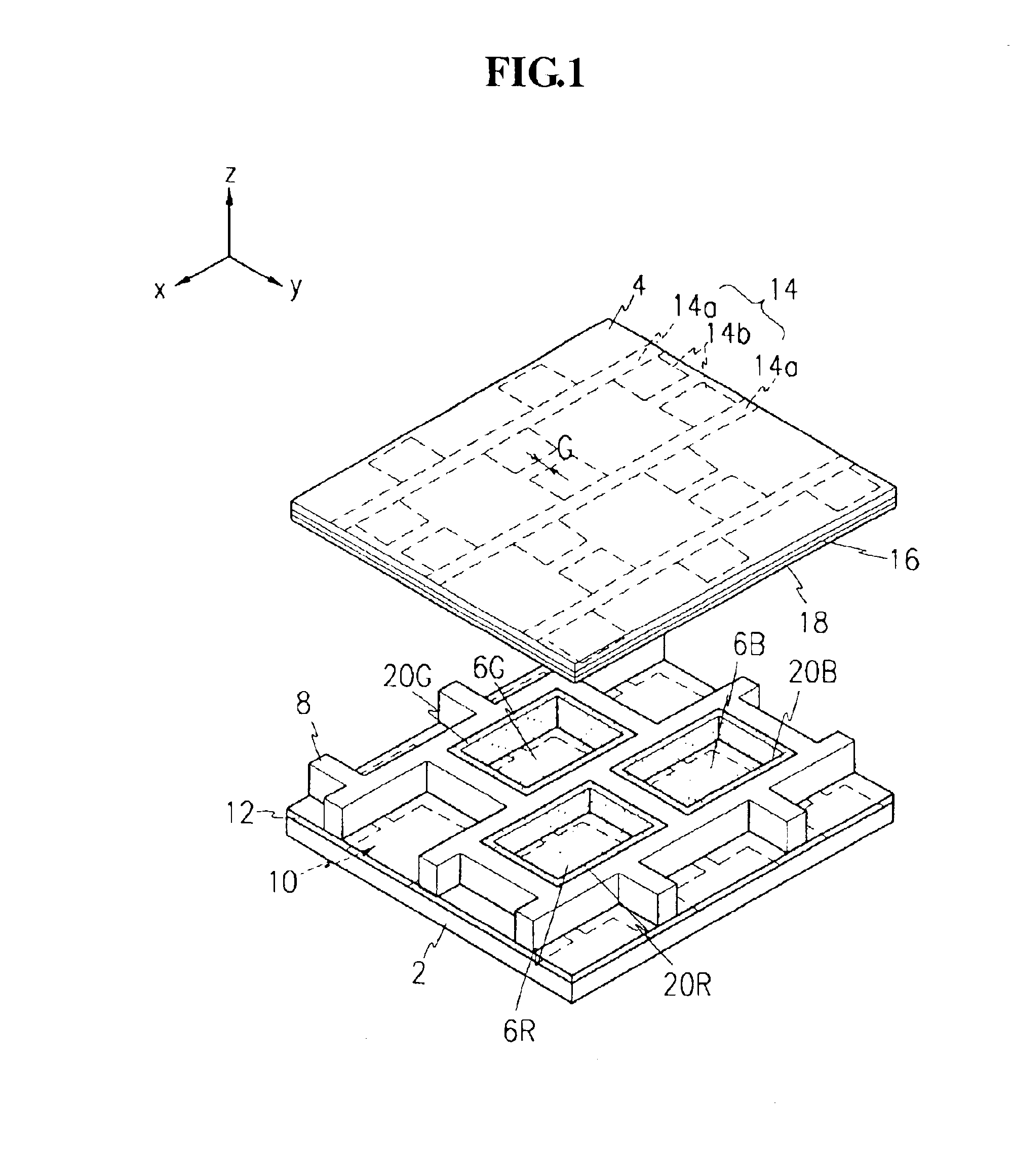
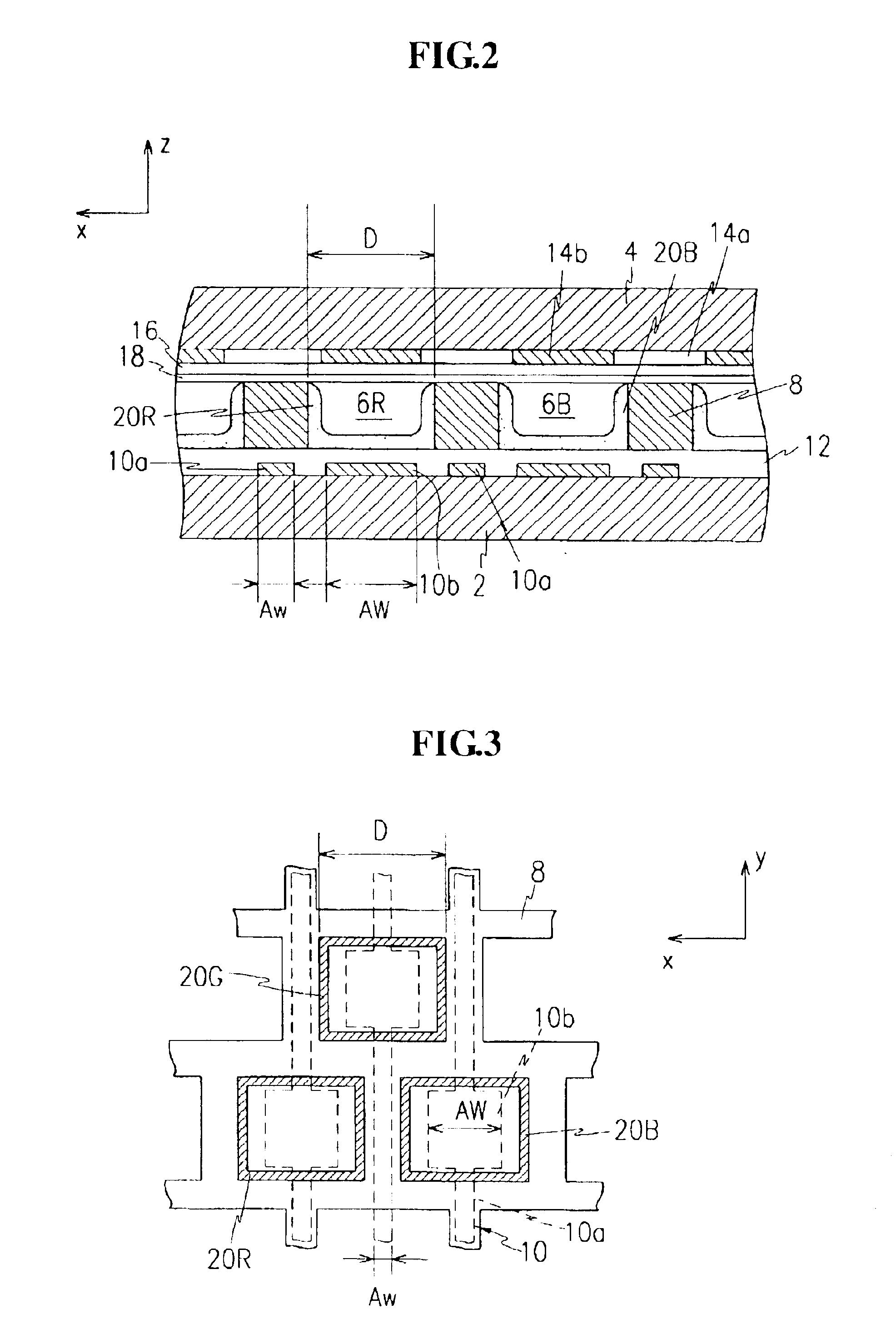
FIG. 1 is a partial exploded perspective view of a plasma display panel according to present invention. FIG. 2 is a partial sectional view of plasma display panel of FIG. 1 in a state where the plasma display panel is assembled.

In a plasma display panel (PDP) according to a first embodiment of present invention, a plurality of R,G,B discharge spaces are defined by sets of barrier ribs, each set forming substantially a triangular shape to realize a delta alternating current PDP. Each discharge space is independently controlled to realize predetermined images.

In more detail, the PDP includes a first substrate 2 (hereinafter referred to as a lower substrate) and a second substrate 4 (hereinafter referred to as an upper substrate). Lower substrate 2 and upper substrate 4 are provided substantially in parallel with a predetermined gap therebetween.

Barrier ribs 8 are provided at a predetermined height between lower substrate 2 and upper substrate 4 in a non-striped pattern. Barrier ribs 8...


PUM


Abstract

A plasma display panel includes a first substrate and a second substrate, the first substrate and the second substrate being provided with a predetermined gap therebetween. Barrier ribs are formed in a non-striped pattern between the first substrate and the second substrate, the barrier ribs defining a plurality of discharge spaces. A plurality of address electrodes are formed on the first substrate along a direction (y), the address electrodes being formed within and outside discharge spaces. A plurality of sustain electrodes are formed on the second substrate along a direction (x), the sustain electrodes being formed within and outside discharge spaces. The address electrodes include large electrode portions provided within discharge spaces and small electrode portions provided outside the discharge spaces. If a width of large electrode portions is AW, a width of small electrode portions is Aw, and a distance between barrier ribs along direction (x) is D, AW is larger than Aw, and AW is 40-75% of D.

Description

CROSS-REFERENCE TO RELATED APPLICATIONSThis application claims priority to Korean Application Nos. 2001-50081, filed on Aug. 20, 2001 and 2001-64767, filed on Oct. 19, 2001 in Korean Patent Office, the entire disclosures of which are incorporated herein by reference.FIELD OF THE INVENTIONThe present invention relates to a plasma display panel, and more particularly, to a plasma display panel having a delta discharge cell arrangement, in which each set of R,G,B discharge cells is formed in a delta shaped configuration.BACKGROUND OF THE INVENTIONA plasma display panel (PDP) is typically a display in which ultraviolet rays generated by the discharge of gas excites phosphors to realize predetermined images. As a result of the high resolution possible with PDPs, many believe that they will become a major, next generation flat panel display configuration.The PDP is classified depending on how its discharge cells are arranged. Two main types of PDPs are: the stripe PDP, in which spaces whe...

Claims


Application Information

Patent Timeline
IPC IPC(8): H01J17/49H01J17/04H01J11/12H01J11/14H01J11/22H01J11/26H01J11/34H01J11/36
CPCH01J11/12H01J11/26H01J11/32H01J2211/326H01J2211/265
Inventor KIM, YONG-JUNYOON, CHA-KEUNSEO, JEONG-HYUNYOO, MIN-SUN
Owner SAMSUNG SDI CO LTD
Why Eureka
Try Eureka