Foldable lift and transfer apparatus for patient

a technology for lifting and transferring equipment, which is applied in the field of patient folding lift and transfer equipment, can solve the problems of increasing the occupying more space in packaging and storage, and achieves the effects of less effort and strength to operate, less force to operate, and reduced length of the whole apparatus

Inactive Publication Date: 2005-02-22
HUANG CHI TZUNG
View PDF1 Cites 107 Cited by
  • Summary
  • Abstract
  • Description
  • Claims
  • Application Information

AI Technical Summary

Benefits of technology

It is a main object of the present invention to provide a foldable lift and transfer apparatus for patient, which is made such that the length thereof can be reduced when it is folded, and such that it takes less effort and strength to operate.
The lift and transfer apparatus for patient has a transfer mechanism, and a lift mechanism; the transfer mechanism includes a support base, two support rods pivoted to the base at rear portions close to rear ends thereof, front wheels connected to front ends of the support rods, rear wheels, and a control member for changing orientation of the support rods with; the lift mechanism includes a post connected to the base at a lower end, a lifting rod pivoted to an upper end of the post, and a lifting hydraulic cylinder for changing height of the lifting rod with. The rear wheels are connected to the support base instead of the support rods so that it takes less force to operate the control member to change orientation of the support rods and the front wheels. The post is formed with a folded portion between two ends while the lifting hydraulic cylinder is supported on a lower end of the folded portion of the post; an upper portion of the main support post is closer to a rear side of the apparatus than a lower portion of the post such that an effort arm of the lifting rod is allowed to be lengthened. The base has an upwards projecting securing portion, which has a locating room defined by front and rear short plates, and left and right inverted L shaped long plates, which each has an inverted L shaped guiding slot; the post is inserted into the locating room at lower end, and secured to the securing portion with bolts, a second one of which bolts is passed through the slots, and the post; thus, the slots allows the post to be displaced towards rear side of the apparatus until the second bolt abuts slot upper rear ends after the other bolts have been removed, and the second bolt loosened, and after the post is pivoted downwards for folding the apparatus, and length of the apparatus, in folded position, can be reduced.

Problems solved by technology

Both of the above lift and transfer apparatuses have a common disadvantage that the support posts will cause increase to the length of the whole apparatuses after they are pivoted down close to the bases for folding the apparatuses because they can't be displaced relative to the bases after the downward pivotal movement.
Consequently, the apparatuses will occupy more space in packaging and storage.

Method used


Image

  • Foldable lift and transfer apparatus for patient
  • Foldable lift and transfer apparatus for patient
  • Foldable lift and transfer apparatus for patient

Examples


Embodiment Construction

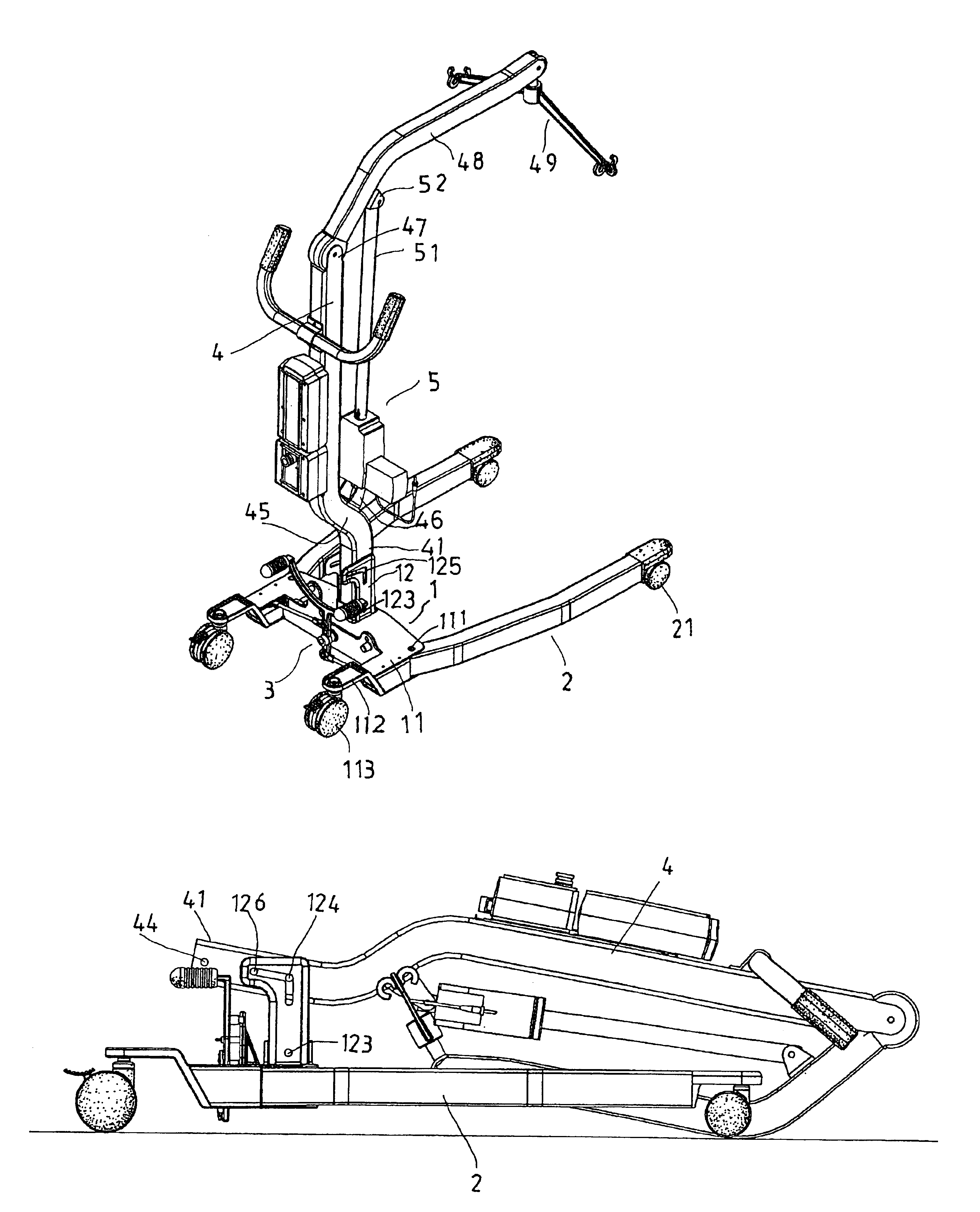
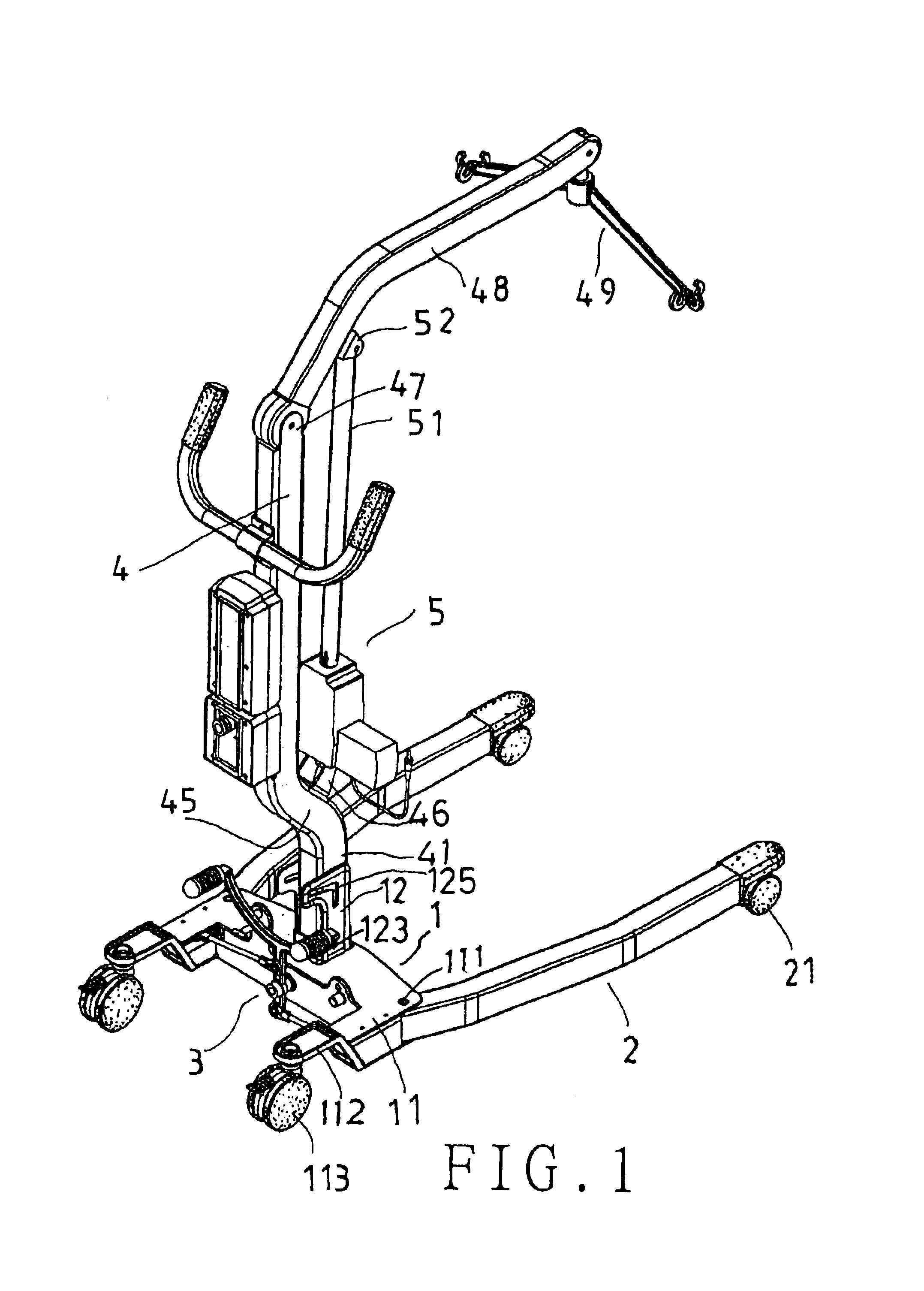
Referring to FIG. 1, a preferred embodiment of a foldable lift and transfer apparatus for patient in the present invention consists of a transferring mechanism, which includes a support base 1, two support rods 2, and a control member 3, and a lifting mechanism, which includes a main support post 4, a lifting rod 48, and a lifting hydraulic cylinder 5.

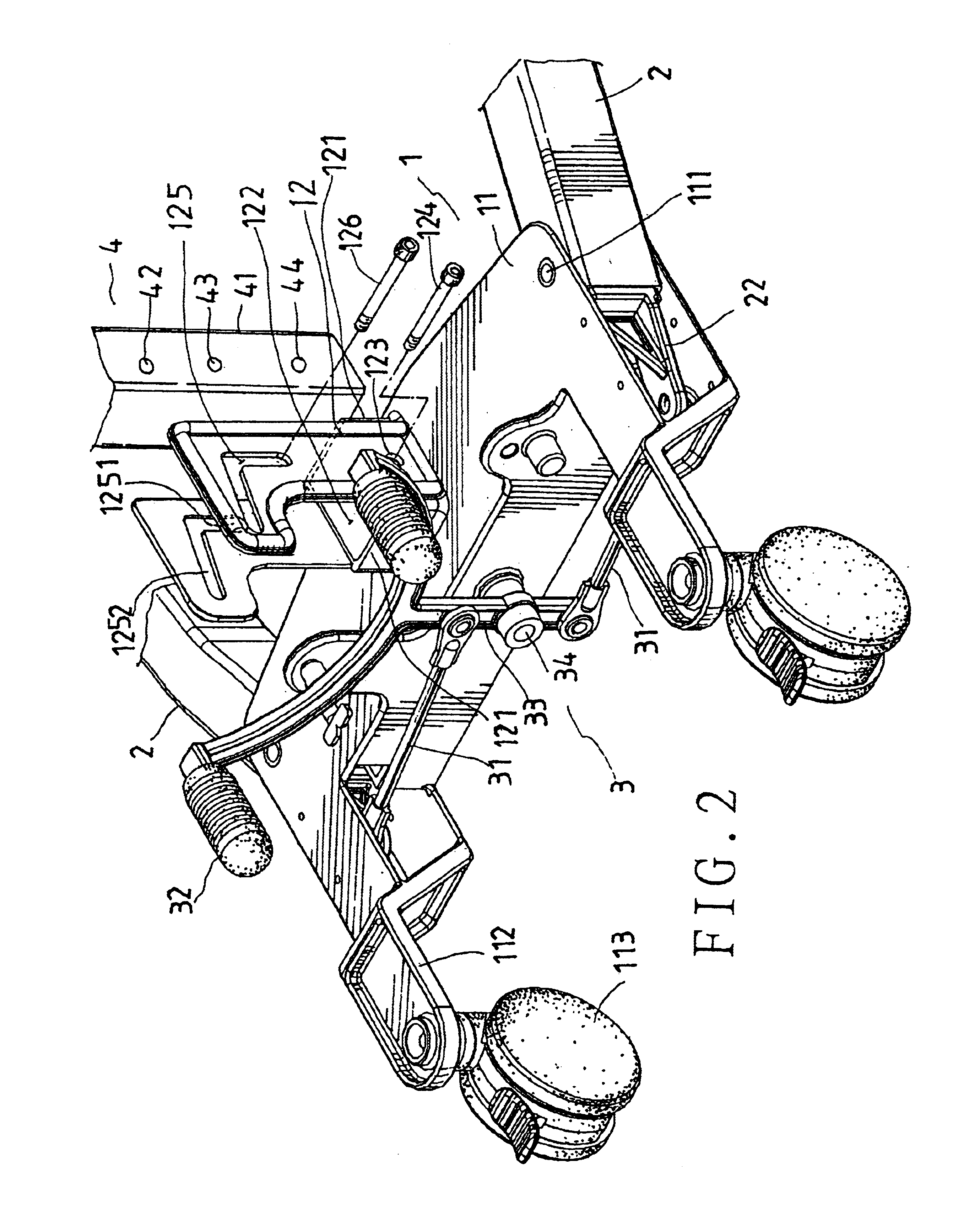
Referring to FIGS. 1, and 2, the support base 1 has upper and lower support plates 11, 11, two extension portions 112 projecting rearwards from the support plates 11, and a securing portion 12 projecting up from the upper support plate 11. The securing portion 12 includes front and rear short plates 121, left and right long plates, which are joined to the edges of the short plates at the edges thereof, and a locating room 122 defined by the short and the long plates. Each of the long plates of the securing portion 12 is formed with an inverted L shape, and has an inverted L shaped guiding slot 125 on an upper portion, and a lower conne...


PUM


Abstract

A lift and transfer apparatus for patient has a wheeled support base, and a main support post; the base has an upwards projecting securing portion, which has a locating room defined by front and rear short plates, and left and right inverted L shaped long plates, which each has an inverted L shaped guiding slot; the post is inserted into the locating room at lower end, and secured to the securing portion with bolts, a second one of which bolts is passed through the slots, and the post; thus, the slots allows the post to be displaced towards rear side of the apparatus until the second bolt abuts slot upper rear ends after the other bolts have been removed, and the second bolt loosened, and after the post is pivoted downwards for folding the apparatus, and length of the apparatus, in folded position, can be reduced.

Description

BACKGROUND OF THE INVENTION1. Field of the InventionThe present invention relates to a foldable lift and transfer apparatus for patient, more particularly one having a lifting mechanism, which can be linearly displaced relative to a lower transferring mechanism so as to further help reduce dimension of the whole apparatus after the apparatus is folded with the lifting mechanism being angularly displaced relative to the lower transferring mechanism.2. Brief Description of the Prior ArtReferring to FIG. 8, a conventional foldable lift and transfer apparatus for patient was devised by inventor of the present invention, which includes a base, a support post pivoted to the base at a lower end, a lifting rod pivoted to an upper end of the support post, a hanging element hung on the lifting rod, and a lifting device. The base has wheels connected to it. The lifting device is pivoted to connecting ears of a middle portion of the support post at a lower end, and has an output rod, which is p...

Claims


Application Information

Patent Timeline
Patent Type & Authority Patents(United States)
IPC IPC(8): A61G7/10
CPCA61G7/1017A61G7/1046A61G7/1074A61G7/1067A61G7/1061
Inventor HUANG, CHI-TZUNG
Owner HUANG CHI TZUNG
Why Eureka
Try Eureka