
Auto-adjusting mask stabilizer

a technology of mask stabilizer and automatic adjustment, which is applied in the direction of breathing mask, breathing protection, respirator, etc., can solve the problems of requiring two hands to adjust, pushing unduly hard on the wearer's nose or face, and adjustment may require too high a level of dexterity for some patients or clinicians, so as to achieve a short amount of time and minimal level of dexterity

Active Publication Date: 2008-12-25
RESMED LTD
View PDF22 Cites 72 Cited by
  • Summary
  • Abstract
  • Description
  • Claims
  • Application Information

AI Technical Summary

Benefits of technology

[0017]One aspect of the invention relates to an auto-adjusting mask stabilizer that permits automatic and / or semi-automatic adjustment of a stabilizer (e.g., a forehead support or facial support) for a mask with a minimal level of dexterity and in a shorter amount of time than is currently possible.
[0019]Still another aspect of the present invention relates to an auto-adjusting mask stabilizer that permits the determination of the ideal mask position, based on comfort and seal, and securement of the ideal position in a shorter amount of time and with less effort than is currently possible.

Problems solved by technology

A problem that arises with the use of the existing masks is that in order for the straps to be tight, the mask is compressed against the wearer's face and may push unduly hard on the wearer's nose or face.
Another problem that arises with the use of existing masks is that many forehead supports require two hands to adjust.
Such an adjustment may require too high a level of dexterity for some patients or clinicians.
In addition, existing mask systems provide discrete adjustment points for the position of the forehead support, leading to a trial and error process in determining the ideal position.
It is also difficult to determine how many discrete positions should be provided.
If too few discrete positions are provided, it may not be able to set or lock the forehead support in a position that truly stabilizes the mask in the ideal position.
If too many discrete positions are provided, the fitting may be complicated by the patient being unable to decide which position stabilizes the mask in the ideal position.
An even further problem with the use of existing masks is that the adjustment of the forehead support changes the inclination between the forehead support pads and the patient's forehead.
Pivoting of the forehead support during the adjustment process changes the inclination between the pad and the patient's forehead and may result in an undesirable change in the amount of support provided by the forehead support.

Method used


Image

  • Auto-adjusting mask stabilizer
  • Auto-adjusting mask stabilizer
  • Auto-adjusting mask stabilizer

Examples


first embodiment

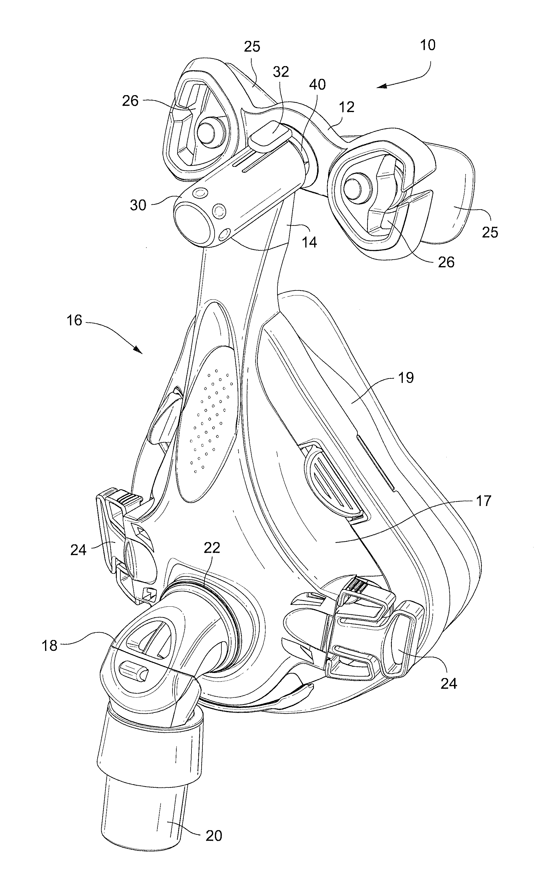
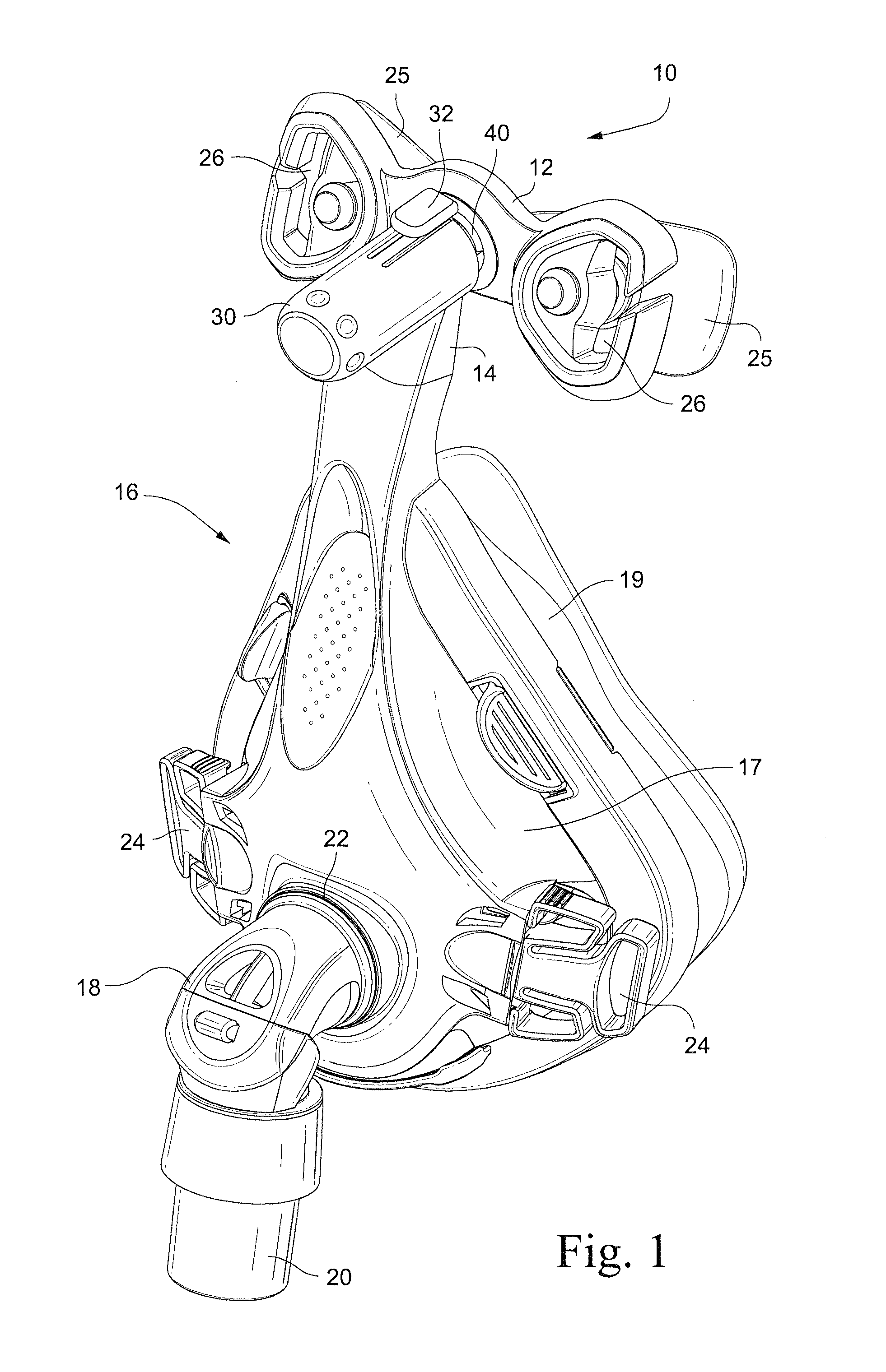
[0048]Referring to FIG. 1, an auto-adjusting mask stabilizer, e.g., forehead support, 10 according to one embodiment of the invention includes a cushion frame 12 mounted to a frame extension 14. The frame extension 14 is connected to, or formed integrally with, a mask 16 used to supply breathable gas to a patient. A separate frame extension allows the auto-adjusting mask stabilizer of the present invention to be adapted to existing mask frames.

[0049]The mask 16 includes a mask frame 17 and a mask cushion 19. The mask frame 17 includes an angled connector 18 (e.g., in the form of a swivel elbow) which has a distal end 20 for connection to a gas supply hose (not shown) and a proximal end 22 for connection to the mask 16. The connector 18 communicates the supplied gas from the gas supply hose to the interior of the mask 16. The mask frame 17 also includes a pair of slotted connectors 24 to which are respectively connected ends of a lower head strap (not shown) for securing the mask 16 ...

second embodiment

[0065]Referring to FIG. 8, according to another embodiment of the invention, a bushing 61 may be provided between the release button 32 and the outer surface of the mask extension cylinder 30. The bushing 61 serves to adjust the force required to depress the release button 32. The bushing 61 may also serve to prevent accidental release of the locking mechanism, for example during movement of the patient during the sleep session. The bushing 61 may also bias the locking mechanism into the locked position.

Alternate Embodiments

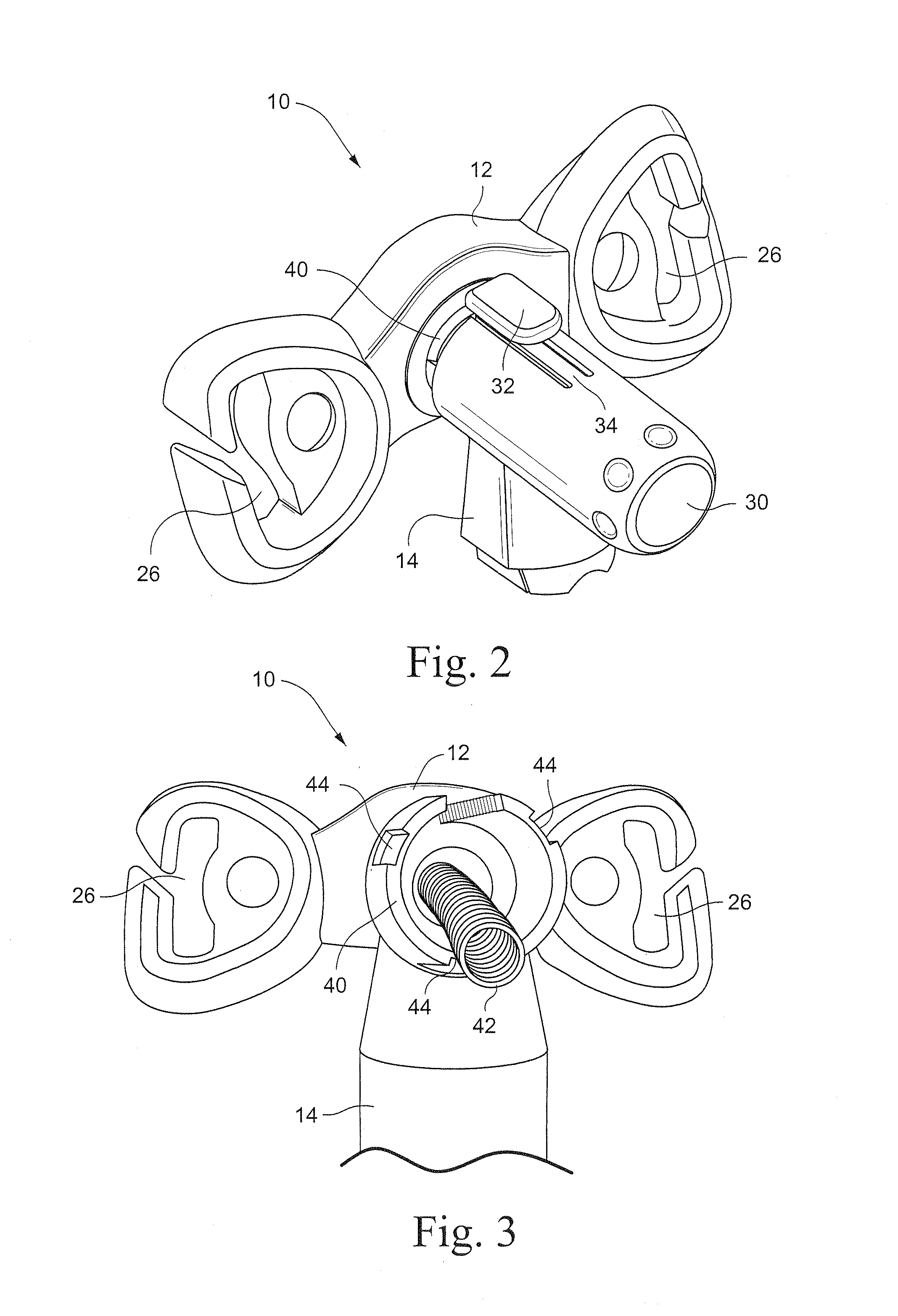
[0066]Although the lock mechanism release button 32 is shown in the attached drawings as being provided on top of the mask frame extension cylinder 30, it should be appreciated that the release button could also be provided anywhere along the circumference of the mask frame extension cylinder 30, with a corresponding movement of the slot 45 and ratchet teeth 46 of the shaft 40 of the cushion frame 12. It should also be appreciated that the release button could be...

third embodiment

[0068]Referring to FIG. 9, an auto-adjusting stabilizer according to another embodiment of the invention includes a frame extension 14a having a frame extension cylinder 30a. A shaft 40a of a cushion frame (not shown) is received in the frame extension cylinder 30a. A biasing element (not shown) is provided between the cylinder 30a and the shaft 40a to bias the shaft 40a relative to the frame 30a.

[0069]Radial projections 38a of the frame extension cylinder 30a frictionally engage the outer surface of the shaft 40a to retain the shaft 40a against movement relative to the cylinder 30a caused by the biasing element. A lock mechanism release button 32a is provided for releasing the engagement of the radial projections 38a from the shaft 40a to permit relative movement between the shaft 40a and the cylinder 30a by the biasing element. Depressing the release button 32a causes the cylinder 30a to deform, thus disengaging the projections 38a from the cylinder 40a.


PUM


Abstract

A forehead support for a facial mask is adapted to be moveable between a first position with respect to a frame of the mask and a second position with respect to the frame. The forehead support includes a biasing mechanism that urges the forehead support in the second position. A method of positioning a forehead support with respect to a frame of a patient interface includes positioning the forehead support and patient interface assembly on a face; disengaging a forehead support locking mechanism; allowing the forehead support to move from a first position to a second position; and engaging a forehead support locking mechanism.

Description

CROSS REFERENCE TO RELATED APPLICATION[0001]This application claims priority to U.S. Provisional Application 60 / 945,380, filed Jun. 21, 2007, the entire contents being incorporated herein by reference.FIELD OF THE INVENTION[0002]Sample embodiments of the present invention relates to an automatically adjusting mask stabilizer for a facial mask used to supply breathable gas to a wearer's airways.[0003]Sample embodiments of the invention have been developed primarily for use in supporting a mask used in Continuous Positive Airway Pressure (CPAP) treatment of, for example, Obstructive Sleep Apnea (OSA) and other ventilatory assistance treatments such as Non-Invasive Positive Pressure Ventilation (NIPPV) and will be described hereinafter with reference to this application. However, it will be appreciated that the sample embodiments of the invention are not limited to these particular uses and are also suitable for use with, for example, nasal (nose only), mouth only, or full-face (i.e. n...

Claims


Application Information

Patent Timeline
IPC IPC(8): A62B18/08
CPCA61M16/06A61M16/0683A61M16/0638A61M16/0622A61M16/0616A61M16/065A61M16/0655
Inventor KWOK, PHILIP RODNEYBRAMBILLA, ENRICOPEAKE, GREGORY ROBERTHENRY, ROBERT EDWARDVELISS, LEE JAMESGUNNING, PHILIP JOHN
Owner RESMED LTD
Learn More