Methods for coating lenses

a technology of coating lenses and lenses, applied in the field of coating lenses, can solve the problems of increased costs, not easily altered, film-based products suffer from certain performance/technology shortcomings, etc., and achieve the effect of short tim

Active Publication Date: 2005-07-07
ESSILOR INT CIE GEN DOPTIQUE
View PDF22 Cites 68 Cited by
  • Summary
  • Abstract
  • Description
  • Claims
  • Application Information

AI Technical Summary

Benefits of technology

[0013] The inventors have developed manners in which to apply polarizing liquids to curved surfaces, including those that have not previously been treated to create an orientation for the polarized coating, and thereafter form polarized coatings. A major benefit afforded by the present methods is that polarized coatings may now be created on made-to-order prescription lenses (e.g., ophthalmic lenses) in a short amount of time. As a result, custom lens makers may now create polarized coatings for their customers on demand, without needing to retain a separate inventory of polarized products.

Problems solved by technology

The final optical properties of the resulting lens are determined by the film and are not easily altered.
Additionally, film-based lenses require a separate inventory of polarized products, which can lead to increased costs.
Film-based products suffer from certain performance / technology shortcomings.
For example, if the polarization axis is not placed within three (3) degrees of the optic axis of a progress lens, the product is not acceptable.
Also, a film placed on a progressive lens can greatly limit the final thickness of a wearer's lens due to the film's thickness.
Furthermore, the precursor film to the polarization film can have cosmetic impurities / non-uniformities due to the nature of dying the polarization film (also known in the art as stretch films).
Such non-uniformity, which can be observed as streaking in the film's coloration, can be exacerbated by the casting process, during which a thermal or chemical attack of the film can lead to dye bleach or further color non-uniformity.
Such a process, commercially, is “dirty” and not readily adaptable or necessarily compatible with all lens materials and curvatures.
The scratching is also likely to induce some haze in the final product.
The patent also does not suggest utilizing shear flow alone in coating a surface with a polarizing liquid.
They are not suited to use on non-flat surfaces.

Method used


Image

  • Methods for coating lenses
  • Methods for coating lenses
  • Methods for coating lenses

Examples


example 1

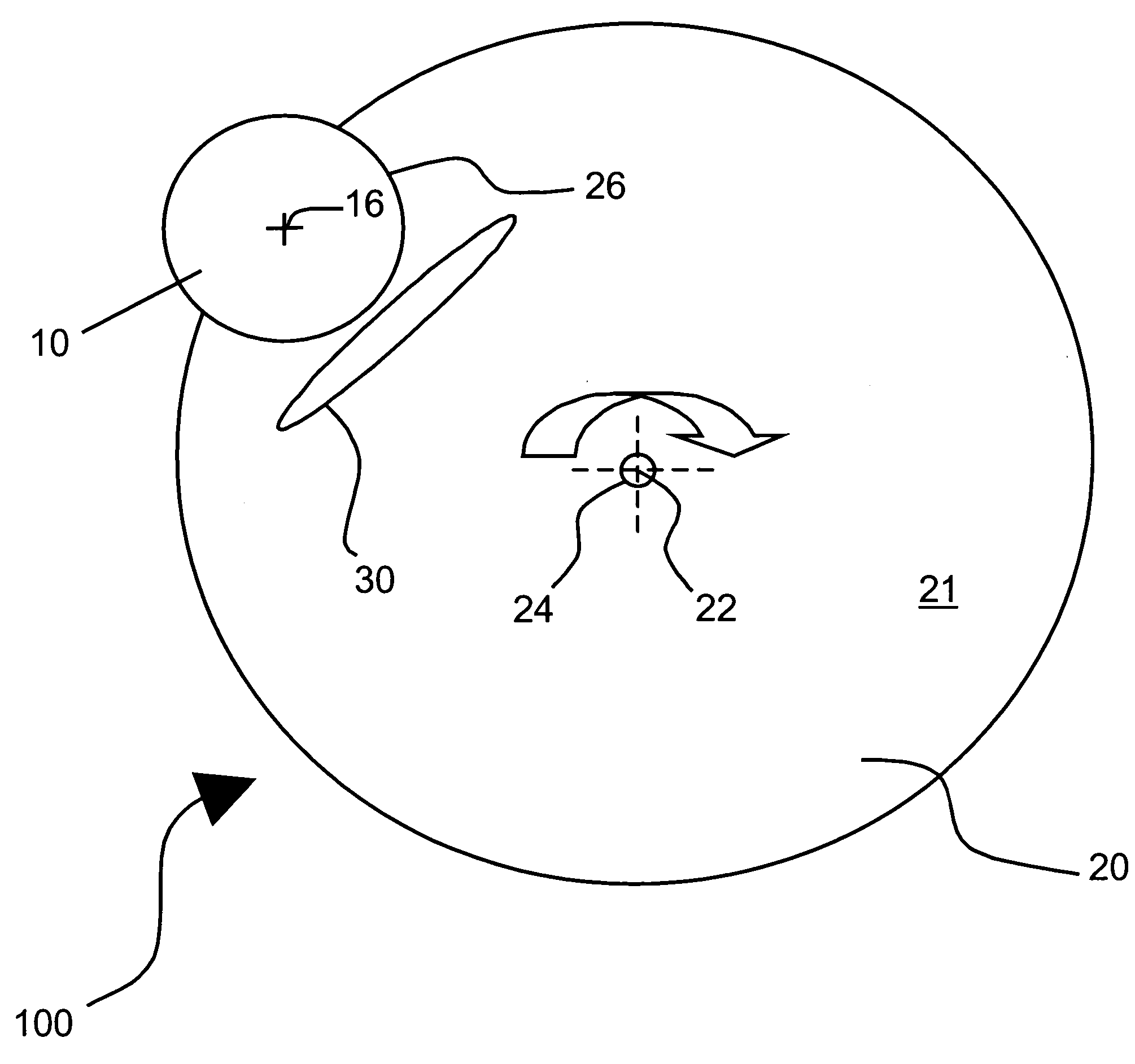
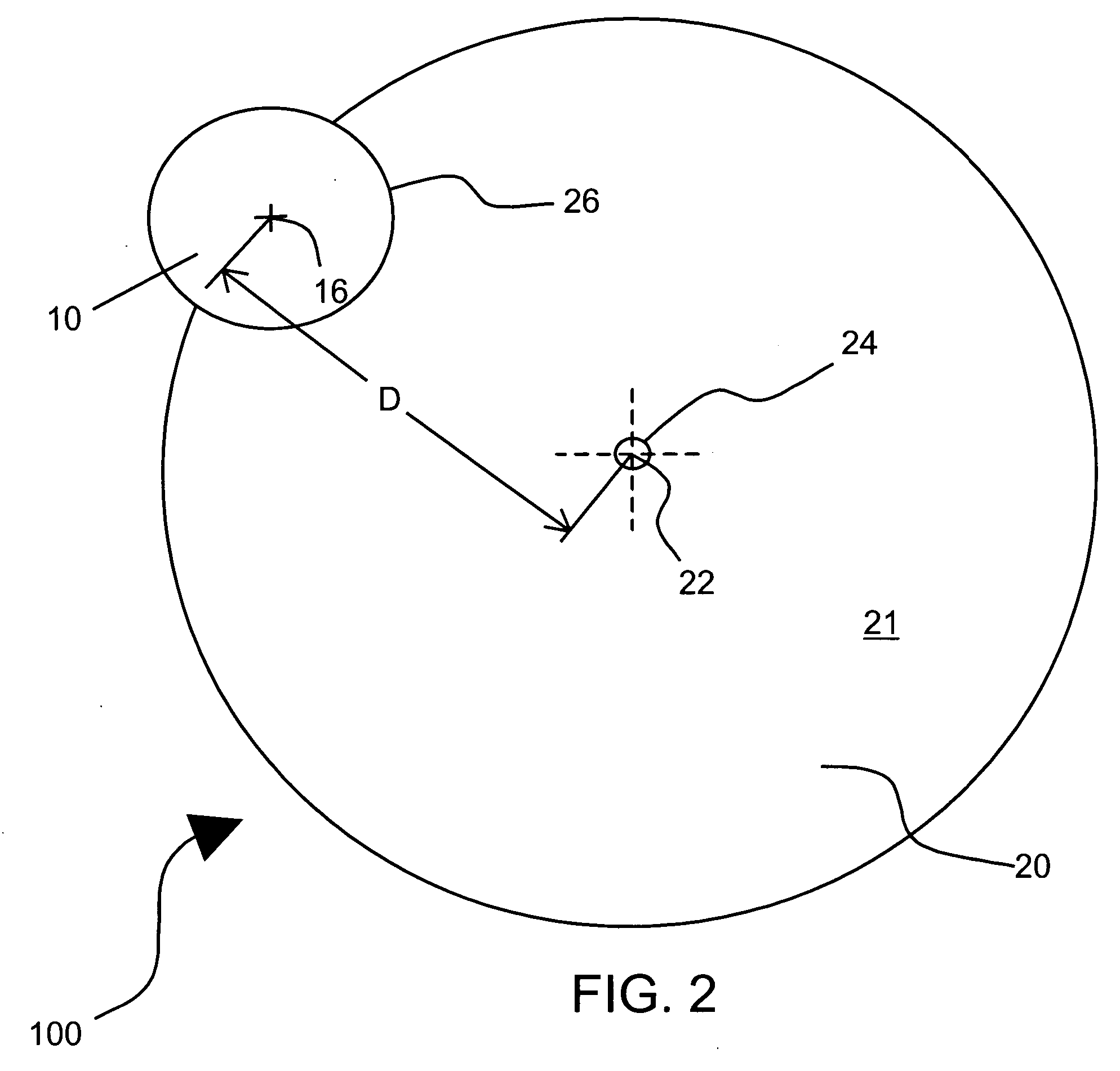
[0073] A substantially circular plastic plate with a diameter of 220 mm was prepared with a notch having a 30 mm in radius located in the edge of the plate. The plate and notch were prepared consistently with setup 100 shown in FIG. 2. A finished single vision 6 base ORMA plano lens (available from Essilor International, and containing diethylene glycol bis (allyl carbonate)) having a convex surface and a substantially opposite concave surface was corona treated using a Model BD-20 handheld unit (Electro Technic Products, Inc., Chicago, Ill.) for approximately 15 seconds to promote adhesion and then placed in the notch (created consistently with the version of notch 26 shown in FIG. 4). The lens was held to the plate using adhesive tape positioned between the concave surface of the lens and the bottom portion of the notch.

[0074] The polarizing liquid used was Optiva's TCF NO15 solution, which is an aqueous dispersion of three self-assembling lyotropic dyes; upon coating, the combin...

example 2

[0078] A substantially circular plastic plate with a diameter of 14 inches was prepared with a notch (which, in this case, was shaped like a complete circle) having a diameter of 70 mm. A generic representation of the plate used in shown in FIG. 7. The notch was positioned entirely inside the plate, as shown in FIG. 7. Specifically, the notch was made by piercing a circular hole having a 60 millimeter (mm) all the way through the plate, and further increasing the size of the hole by circularly removing material only in its upper part to reach a diameter of 70 mm through a depth of 3 mm from the top surface of the plate. The notch thus comprises in its upper part an annular recess (70 mm diameter) and in its lower part an annular flange (60 mm diameter) on which the lens was supported at the lens periphery.

[0079] The same lenses were used in this example as were used in Example 1; the same corona treatment was applied to those lenses; and the same amount of the same polarizing liqui...

example 3

[0082] The inventors have discovered that conventional spin coating may be employed in combination with the off-centered spin coating described in this disclosure to yield suitable polarized coatings on lenses. In this example, the same types of lenses used for Examples 1 and 2 were first placed on the Headway Research, Inc. spin coating machine referenced above and rotated about their own axes at the rates and times listed below in Table 2. The rotating occurred at 21° C. and at a relative humidity of approximately 60%. The same polarizing liquid used for Examples 1 and 2 was used for the lenses in this example.

[0083] Following the traditional spin coating, and while the polarizing liquid was still wet, the lenses were placed on the plate used for Example 2 and rotated at the rates and for the times provided below in Table 2. The coated lenses then sat at 21° C. and a relative humidity of approximately 60% to dry. The lenses were then immersed in a 10% barium chloride aqueous solu...


PUM

PropertyMeasurementUnit
acute angleaaaaaaaaaa

Abstract

Methods of coating at least a portion of a curved surface of a lens with a polarizing liquid. One method includes providing a lens having a curved surface and a lens axis; and rotating the lens about a rotation axis such that a polarizing liquid flows over at least a portion of the curved surface; the rotation axis being offset from the lens axis. Other methods are included. Apparatuses include ophthalmic lenses having polarized coatings formed according to any of the disclosed methods.

Description

BACKGROUND OF THE INVENTION [0001] 1. Field of the Invention [0002] The invention relates generally to methods of coating lenses. More particularly, the invention relates to methods of applying polarized coatings to curved lenses. [0003] 2. Description of Related Art [0004] Polarized lenses block light of certain polarization states. By blocking horizontally polarized light, a polarized lens reduces glare that would otherwise exist through a non-polarized lens, such as glare off water, roads, and other objects. As a result of the reduced glare, objects become more distinct and true colors more clear. There are currently several different known systems for polarizing lenses for use in eyewear. [0005] a. Film-Based Polarizing Systems [0006] Certain of today's current eyewear products are fabricated by casting polyvinylalcohol-iodine films into a thermoset lens or by insert injection molding of a laminated polarized film to a thermoplastic lens. From a business perspective, these techn...

Claims


Application Information

Patent Timeline
Patent Type & Authority Applications(United States)
IPC IPC(8): B05C11/08B05D1/00B05D3/10B29D11/00G02B5/30G02C7/12
CPCB05C11/08
Inventor MUISENER, RICHARDCHAPUT, FEDERICMOSSE, HERBERT
Owner ESSILOR INT CIE GEN DOPTIQUE
Why Eureka
Try Eureka