Eye therapy system

a technology of eye therapy and thermokeratoplasty, applied in the field of keratoplasty, can solve the problems of affecting the healing period, and affecting the healing effect of the outer layer, and achieves the effects of reducing the healing period, and reducing the healing

Inactive Publication Date: 2009-03-12
AVEDRO
View PDF49 Cites 67 Cited by
  • Summary
  • Abstract
  • Description
  • Claims
  • Application Information

AI Technical Summary

Benefits of technology

[0008]In view of the foregoing, embodiments of the present invention provide a system that selectively applies coolant to the corneal surface to minimize heat-related damage to the corneal surface during thermokeratoplasty and to determine the depth of heating below the corneal surface.
[0017]In addition to delivering micro-controlled pulses of coolant, some embodiments may deliver pulses of energy. In particular, the embodiments may employ high power energy to generate heat in a targeted region of the eye in a relatively short amount of time. To minimize unwanted diffusion of heat, the duration of the energy pulse may be shorter than the thermal diffusion time in the targeted region of the eye. In an exemplary application: a first pulse of coolant is delivered to reduce the temperature of the corneal surface; a high power pulse of microwave energy is then applied to generate heat within selected areas of collagen fibers in a mid-depth region; and a second pulse of coolant is delivered in sequence to end further heating effect and “set” the corneal changes that are caused by the energy pulse.

Problems solved by technology

However, such surgical procedures typically require a healing period after surgery.
Furthermore, such surgical procedures may involve complications, such as dry eye syndrome caused by the severing of corneal nerves.
Therefore, the maximum temperature can occur at the corneal surface, resulting in possible heat-related injury and damage to the outer layer, known as the epithelium, at the corneal surface.
Moreover, devices for thermokeratoplasty may provide inadequate approaches for controlling the depth of heating below the corneal surface and promoting sufficient heating of the targeted collagen fibers while minimizing the application of heat to areas outside the targeted collagen fibers.

Method used


Image

  • Eye therapy system
  • Eye therapy system
  • Eye therapy system

Examples


Embodiment Construction

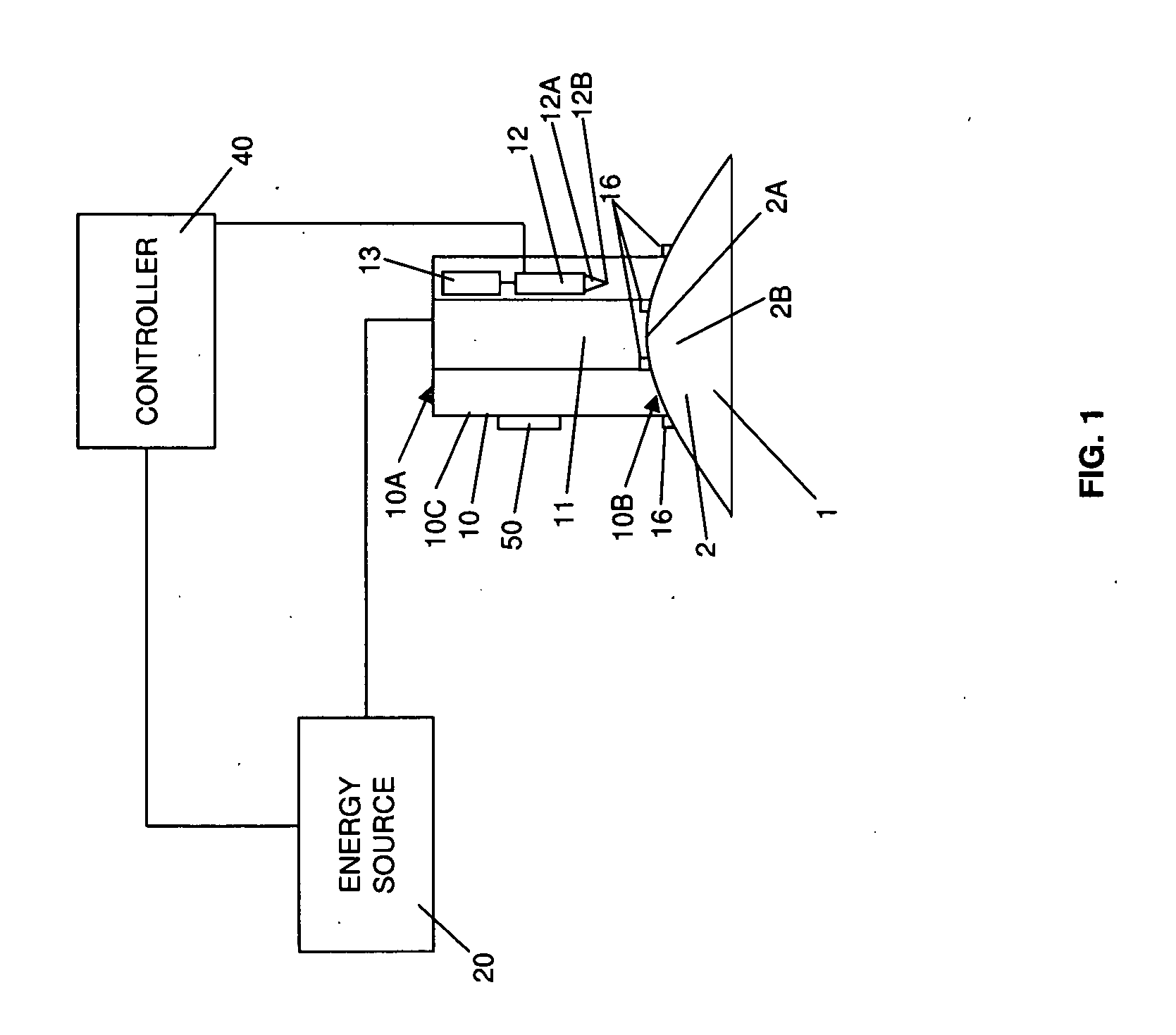
[0040]Referring to FIG. 1, an embodiment of the present invention is schematically illustrated. In particular, FIG. 1 shows an applicator 10 operably connected to an energy source 20. The applicator 10 includes an energy conducting element 11, which extends from the proximal end 10A to the distal end 10B of the applicator 10. The applicator 10 may be connected to the energy source 20 at the proximal end 10A. Operation of the energy source 20 causes energy to be conducted through the energy conducting element 20 and heat to be generated at the distal end 10B. As such, the applicator 10 may be employed to apply heat to a cornea 2 of an eye 1 that is positioned at or near the distal end 10B. In particular, the heat is applied to selected areas of collagen fibers in a mid-depth region 2B of the cornea 2 to shrink the collagen fibers according to a predetermined pattern and reshape the cornea 2, thereby improving vision through the eye 1.

[0041]As further illustrated in FIG. 1, the applic...


PUM


Abstract

A system for applying therapy to an eye selectively applies coolant to the corneal surface to minimize heat-related damage to the corneal surface during thermokeratoplasty. Embodiments may include an energy source, a conducting element, a coolant supply, and a coolant delivery system. The conducting element is operably connected to the energy source and extends from a proximal end to a distal end. The conducting element directs energy from the energy source to the distal end, which is positionable at the eye. The coolant delivery system is in communication with the coolant supply and is operable to deliver a micro-controlled pulse of coolant to the distal end.

Description

CROSS REFERENCE TO RELATED APPLICATIONS[0001]This application is a Continuation-In-Part (CIP) Application of U.S. application Ser. No. 11 / 898,189, filed Sep. 10, 2007, which claims the benefit of U.S. Provisional Application No. 60 / 929,946 filed Jul. 19, 2007, the contents of these applications being incorporated herein by reference.BACKGROUND OF THE INVENTION[0002]1. Field of the Invention[0003]The invention pertains to the field of keratoplasty and, more particularly, to thermokeratoplasty and the application of coolant to the eye during thermokeratoplasty.[0004]2. Description of Related Art[0005]A variety of eye disorders, such as myopia, keratoconus, and hyperopia, involve abnormal shaping of the cornea. Keratoplasty reshapes the cornea to correct such disorders. For example, with myopia, the shape of the cornea causes the refractive power of an eye to be too great and images to be focused in front of the retina. Flattening aspects of the cornea's shape through keratoplasty decr...

Claims


Application Information

Patent Timeline
Patent Type & Authority Applications(United States)
IPC IPC(8): A61F9/007
CPCA61B18/1477A61H2230/50A61B18/22A61B2018/00702A61B2018/00791A61B2018/1425A61B2018/1807A61F9/007A61F9/0079A61F9/009A61F2009/00853A61F2009/00872A61H35/02A61H2201/0207A61H2201/0214A61H2201/0242A61H2201/0292A61H2201/10A61H2201/5007A61B18/18A61B18/12A61B2018/00005
Inventor MULLER, DAVIDSCHARF, RONALDRYAN, THOMASMARSHALL, NEALPERTAUB, RADHAWU, ARTIE
Owner AVEDRO
Why Eureka
Try Eureka