
Roof retaining apparatus

Inactive Publication Date: 2005-02-22
BRANTER JEROME
View PDF13 Cites 20 Cited by
  • Summary
  • Abstract
  • Description
  • Claims
  • Application Information

AI Technical Summary

Problems solved by technology

However, to date no one has yet proposed the roof retaining apparatus which both creates a scaffold and has a net thereabove, with as many apparatus as necessary being engageable one to the other so as to accommodate any required expanse of roof.

Method used


Image

  • Roof retaining apparatus
  • Roof retaining apparatus
  • Roof retaining apparatus

Examples


Embodiment Construction

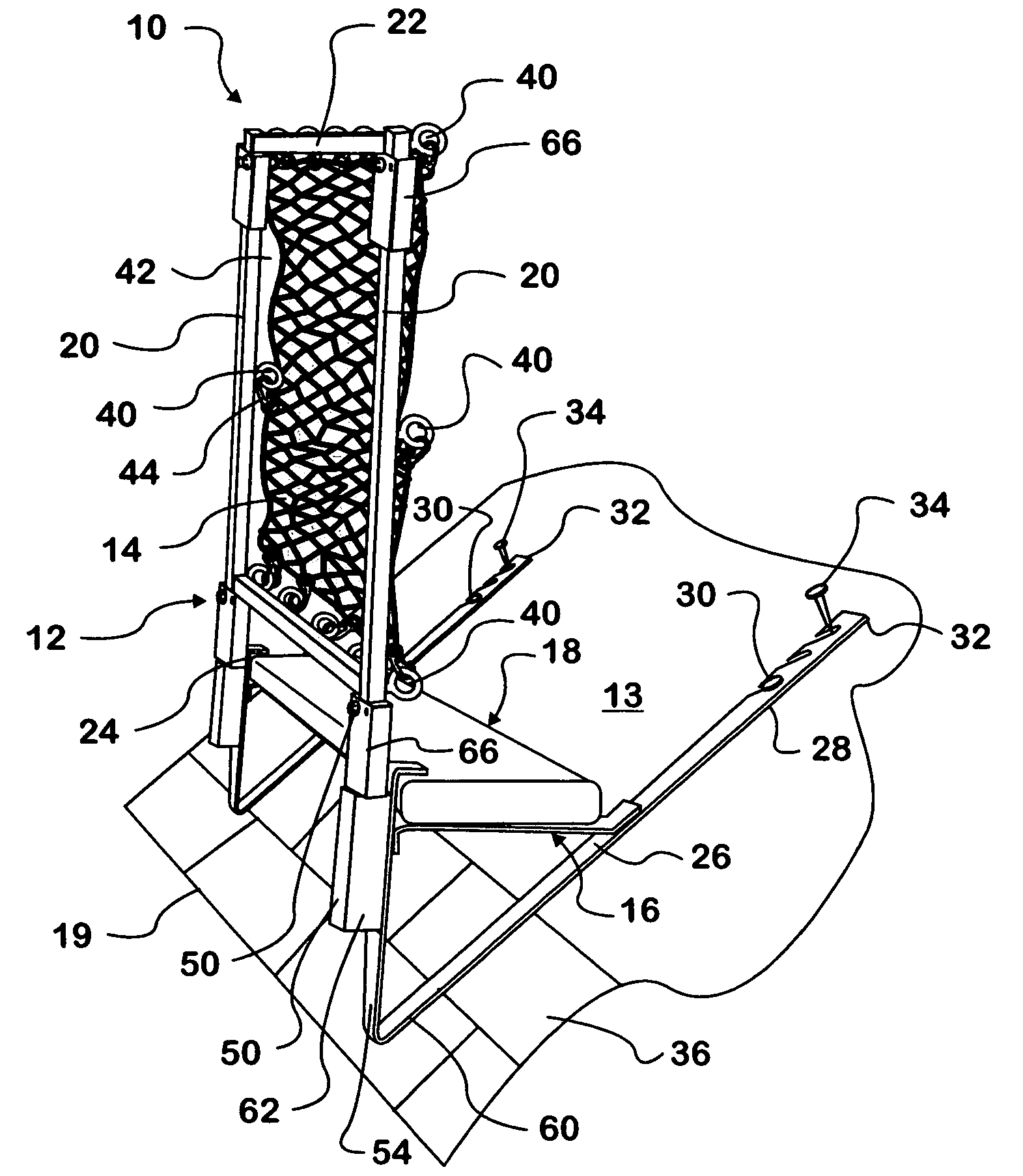
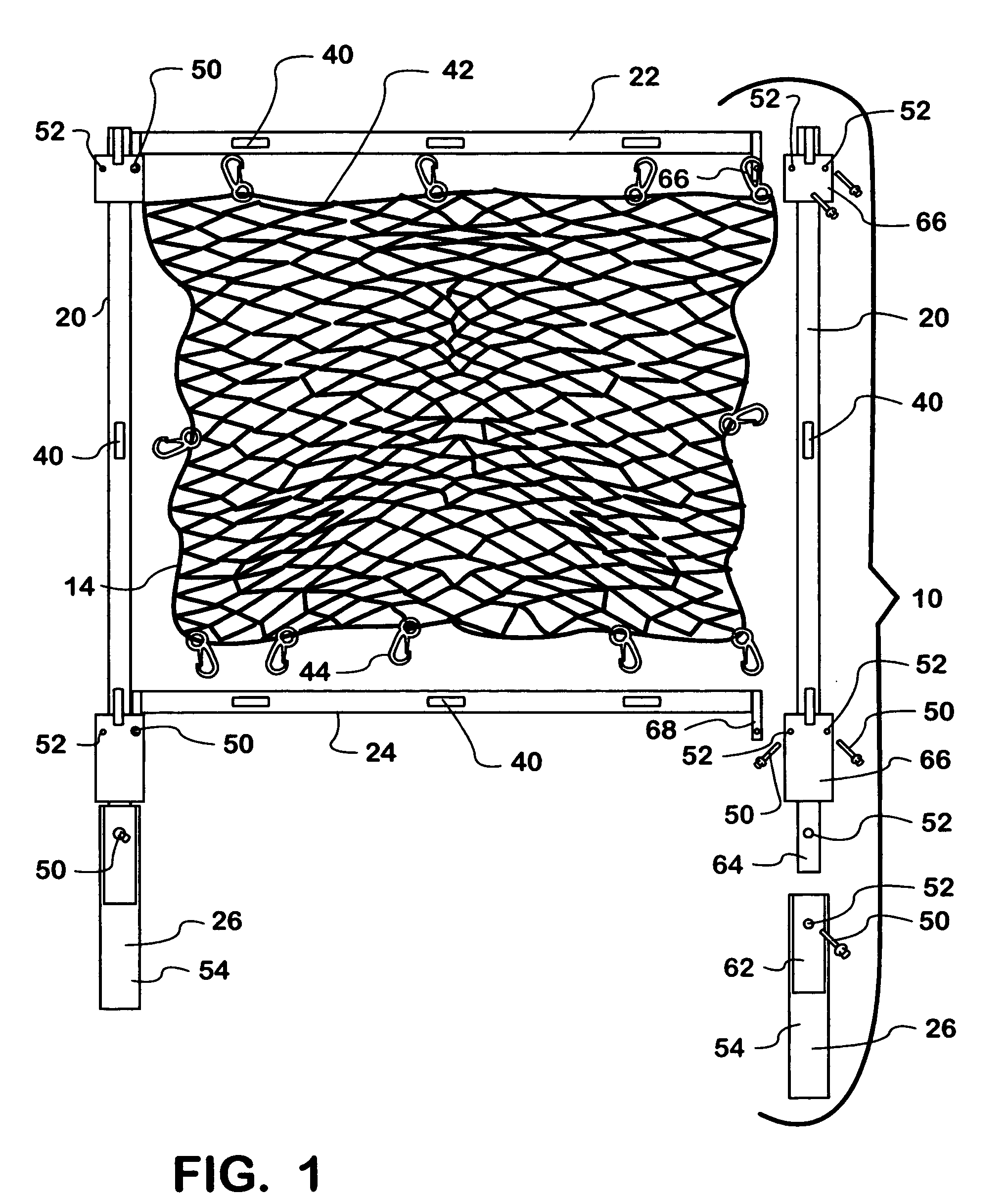
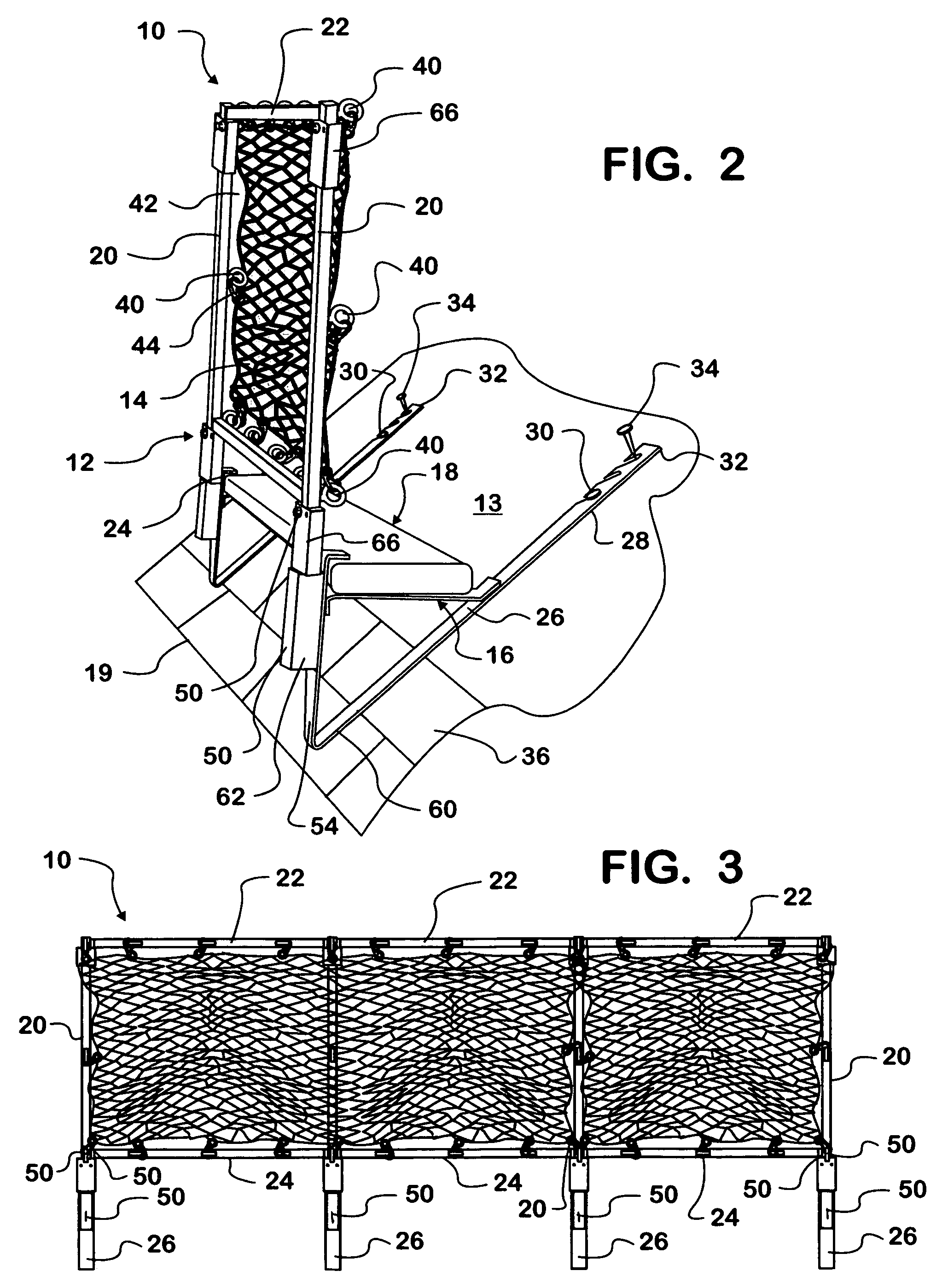
Referring now to the drawings in greater detail there is illustrated therein a roof retaining apparatus made in accordance with the teachings of the present invention and generally identified by the reference numeral 10.

As shown in the apparatus 10 comprises a framework 12 which is adapted to engaged a slanted roof 13 (FIG. 2), a net 14 and a structure 16 (FIG. 2) used in creating a scaffold 18 upon which a roofer may stand near a bottom edge 19 of the roof 13.

The framework 12 includes two upstanding posts or uprights 20 to which at least one top cross member 22 and one bottom cross member 24 is engageable.

The upstanding posts 20 themselves engage angulated roof engaging arms 26 which arms 26 each further support the structure 16, in the form of a brace element 16, which cooperate to form and support the scaffold 18, positioned proximate to the bottom cross member 22.

The arms 26 each include an elongated planar portion 28 which flushly overlies the roof 13 and engages to the roo...


PUM


Abstract

The apparatus comprises a framework having two angled arms, one flat portion of each arm adapted to be fixed to a rooftop. An upright extends upwardly from each arm and top and bottom cross members extend between and are fixed to the arms. Multiple arms, uprights and cross members are joinable together to accommodate a rooftop of any lateral extent. A net extends across the area defined by and between the uprights and cross members. Also, the arms include brace structure adapted for engaging scaffolding thereacross.

Description

BACKGROUND OF THE INVENTION 1. Field of the Invention The present invention relates to a roof retaining apparatus. More particularly, the retaining apparatus incorporates at least a framework with netting stretched thereacross, the framework being fixable to a slanted roof structure to keep debris and workers from falling therepast. 2. Prior Art Heretofore various apparatus have been proposed for maintaining things, and persons, on a slanted rooftop. For example, U.S. Pat. No. 5,749,438 discloses a protective device mounted at the base of a roof and comprising a framework upon which a net is engaged, the framework being held in position by bracing wires engaged to the roof. Still further, U.S. Pat. No. 6,220,390 discloses a rooftop scaffolding system which engages a slanted roof and has a moveable platform thereon upon which a worker stands. Yet further, U.S. Pat. No. 4,805,735 discloses a guard system for a scaffolding arrangement which includes a net wall spanning gap between uppe...

Claims


Application Information

Patent Timeline
IPC IPC(8): E04G3/26E04G21/32
CPCE04G21/3214E04G3/26E04G21/3266
Inventor BRANTER, JEROME
Owner BRANTER JEROME
Learn More