Rotary compressor

a compressor and rotary technology, applied in the direction of positive displacement liquid engines, piston pumps, liquid fuel engines, etc., can solve the problems of high cost of inverter circuits, compressor breakage, and excessive vacuum generation

Inactive Publication Date: 2005-03-01
SAMSUNG ELECTRONICS CO LTD
View PDF7 Cites 41 Cited by
  • Summary
  • Abstract
  • Description
  • Claims
  • Application Information

AI Technical Summary

Benefits of technology

FIG. 26 is a view showing the operational effect of the first and second roller pistons having the reliefs shown in FIGS. 24 and 25.

Problems solved by technology

However, the conventional rotary compressor having the double cylinder structure has a problem that excessive vacuum may be generated in the discharge part 21b of the cylinder 106 when the rotating shaft 101 is rotated in a reverse direction, so the compressor may be broken.
Thus, an expensive inverter circuit is required to vary a compression capacity of such a compressor.
Moreover, a control board is additionally required to control the inverter circuit, thus undesirably increasing a production cost of the compressor and increasing power consumption when the compressor is operated.
However, such a construction is applied to only a reciprocating compressor.
Substantially, there has not been developed a rotary compressor having a construction for varying a compression capacity as desired.
In addition, the design of a rotary compressor having a construction which varies a compression capacity has been recognized as being very difficult.

Method used


Image

  • Rotary compressor
  • Rotary compressor
  • Rotary compressor

Examples


Embodiment Construction

Reference will now be made in detail to the embodiments of the present invention, examples of which are illustrated in the accompanying drawings, wherein like reference numerals refer to like elements throughout.

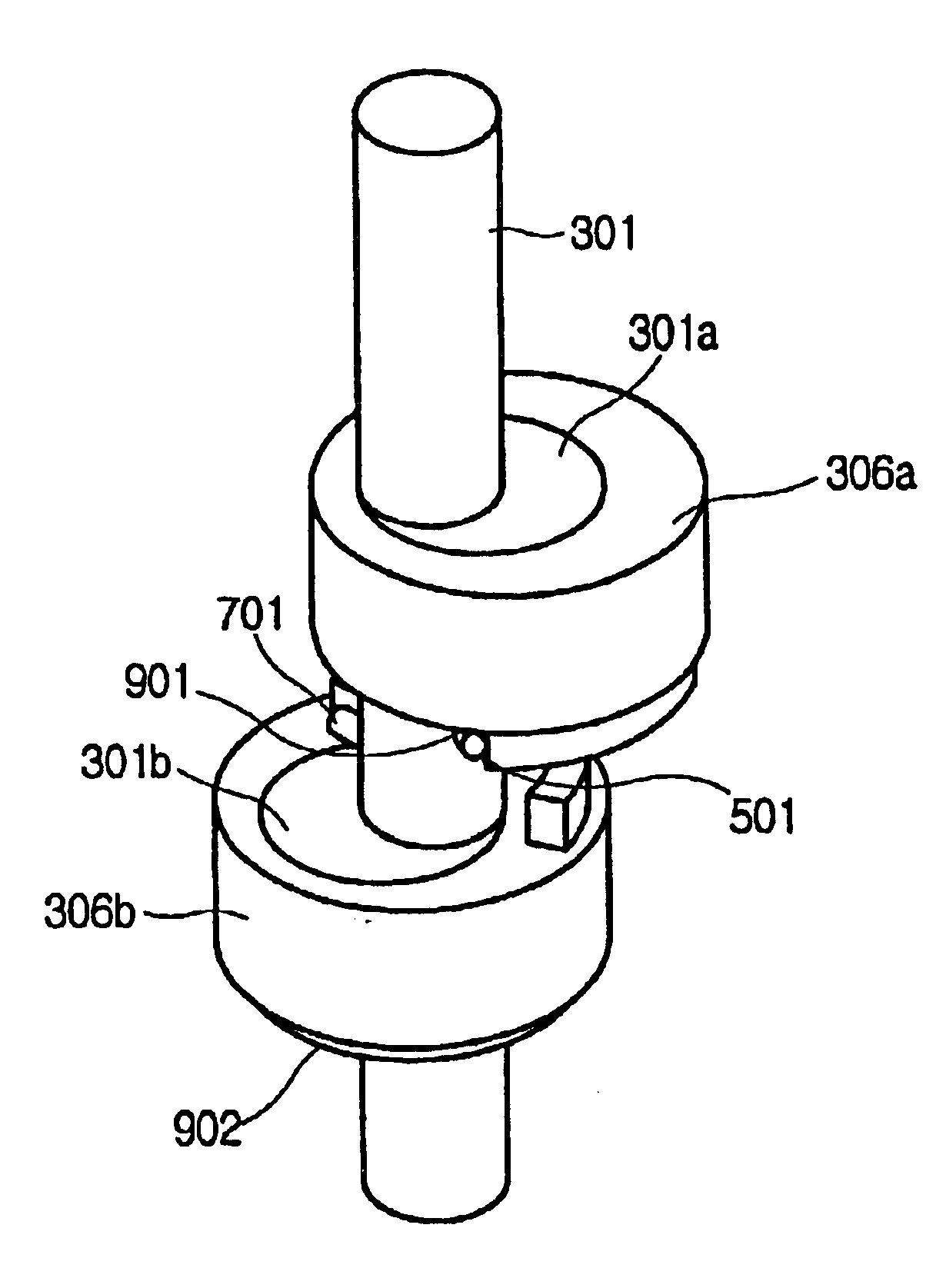
FIG. 3 is a side sectional view showing a rotary compressor according to an embodiment of the present invention. As shown in FIG. 3, the rotary compressor includes a hermetic casing 300 which defines an external envelope and an appearance of the compressor. A drive unit 30 and a compressing unit 31 are housed in the casing 300. A rotating shaft 301 is set at a center of the drive unit 30, and is provided with first and second eccentric parts 301a and 301b. A rotor 302 is mounted to the rotating shaft 301, and is rotated by an electromagnetic force generated by an interaction of a permanent magnet which is buried in or attached to the rotor 302 and an electromagnet formed in a stator 303. The stator 303 surrounds the rotor 302 at a position which is spaced apart from the roto...


PUM


Abstract

A rotary compressor having a plurality of compression chambers and adapted to vary a compression capacity according to a direction of rotation of roller pistons within the compression chambers. A rotating shaft provided with a plurality of eccentric parts drives the roller pistons to compress refrigerant in the compression chambers by eccentric rotations of the eccentric parts. A reversible motor selectively rotates the rotating shaft in opposite directions, and a clutch engages the roller pistons such that the roller pistons perform a compressing action or an idle action according to a rotating direction of the rotating shaft, thus varying the compression capacity of the compressor according to a rotating direction of the rotating shaft. Thus, the compression capacity may be varied without using an inverter circuit.

Description

CROSS-REFERENCE TO RELATED APPLICATIONThis application claims the benefit of Korean Application No. 2002-61462, filed Oct. 9, 2002, in the Korean Intellectual Property Office, the disclosure of which is incorporated herein by reference.BACKGROUND OF THE INVENTION1. Field of the InventionThe present invention relates, in general, to a rotary compressor having a plurality of cylinders and, more particularly, to a rotary compressor which varies a compression capacity as desired, by selectively engaging one or a plurality of roller pistons according to a direction of rotation of a rotating shaft which drives the rotating pistons.2. Description of the Related ArtAs is well known to those skilled in the art, compressors are widely used in a variety of refrigeration systems, such as refrigerators and air conditioners. In such refrigeration systems, the compressor compresses refrigerant to highly pressurize the refrigerant prior to discharging the high-temperature and high-pressure refriger...

Claims


Application Information

Patent Timeline
Patent Type & Authority Patents(United States)
IPC IPC(8): F04C23/00F04C18/356F04C28/06F04C28/08F04C29/00
CPCF04C23/001F04C28/06F04C29/0057F04C23/008F04C18/3562F04C2240/403F04C29/00
Inventor CHO, SUNG-HEAPARK, SUNG-YEONJUNG, CHANG-HOKIM, JONG-GOO
Owner SAMSUNG ELECTRONICS CO LTD
Why Eureka
Try Eureka