Eccentric spiral antenna and method for making same

a spiral antenna and antenna technology, applied in the direction of non-resonant long antennas, antenna supports/mountings, radiating element structural forms, etc., can solve the problems of inability to configure antennas to deliver the required functionality and be more compact in time and material cos

Inactive Publication Date: 2005-03-01
AVAGO TECH INT SALES PTE LTD
View PDF5 Cites 20 Cited by
  • Summary
  • Abstract
  • Description
  • Claims
  • Application Information

AI Technical Summary

Benefits of technology

A still further embodiment of the present invention provides a method including spacing spiral portions of an elongated spiral antenna a first predetermined distance from each other in a contracted section. The method also includes spacing the spiral portions of the elongated spira

Problems solved by technology

These are costly in both time and materials.
Also, as telecommunications devices become smaller and more m

Method used


Image

  • Eccentric spiral antenna and method for making same
  • Eccentric spiral antenna and method for making same
  • Eccentric spiral antenna and method for making same

Examples


Embodiment Construction

Elongated Spiral Antenna

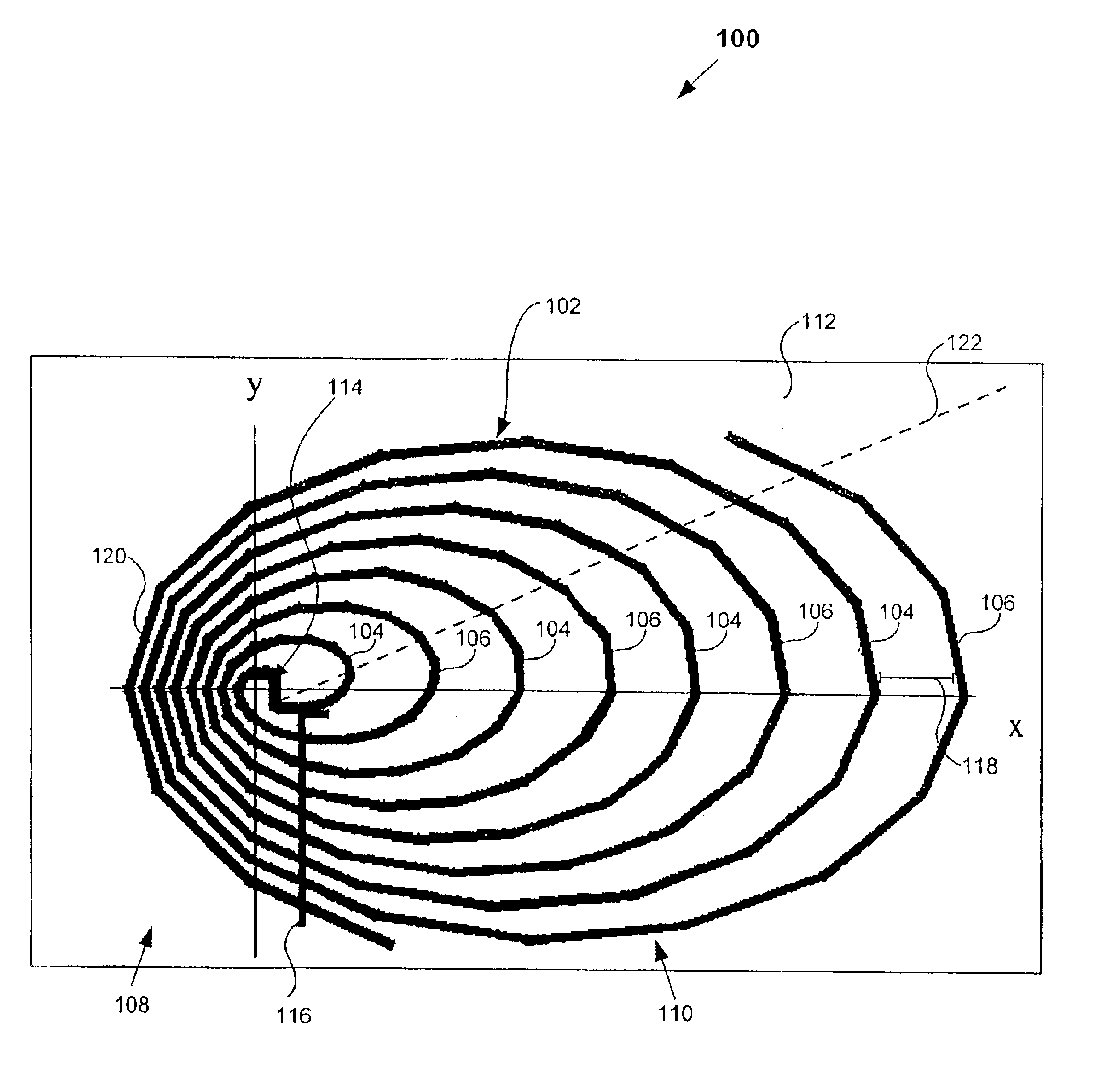
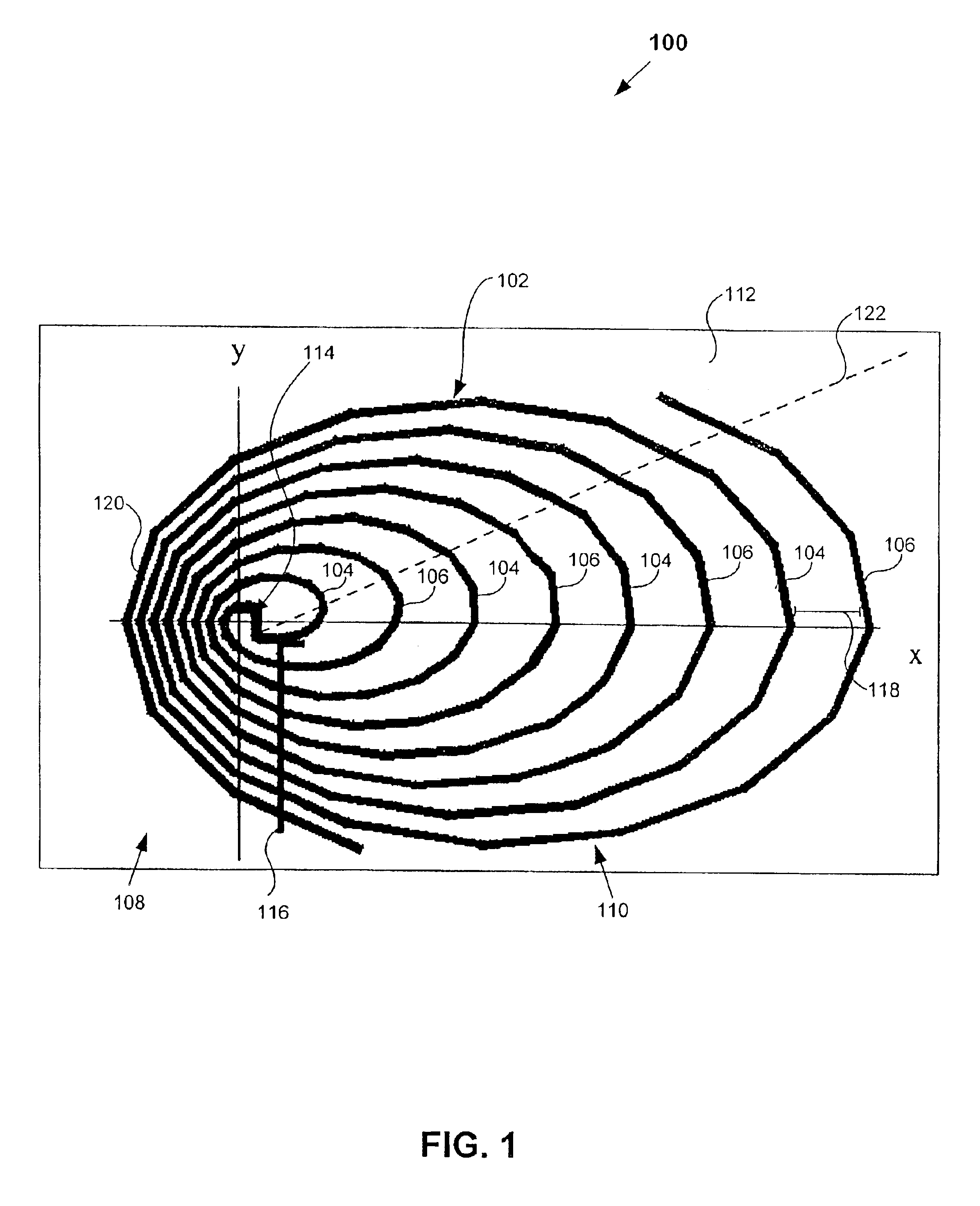
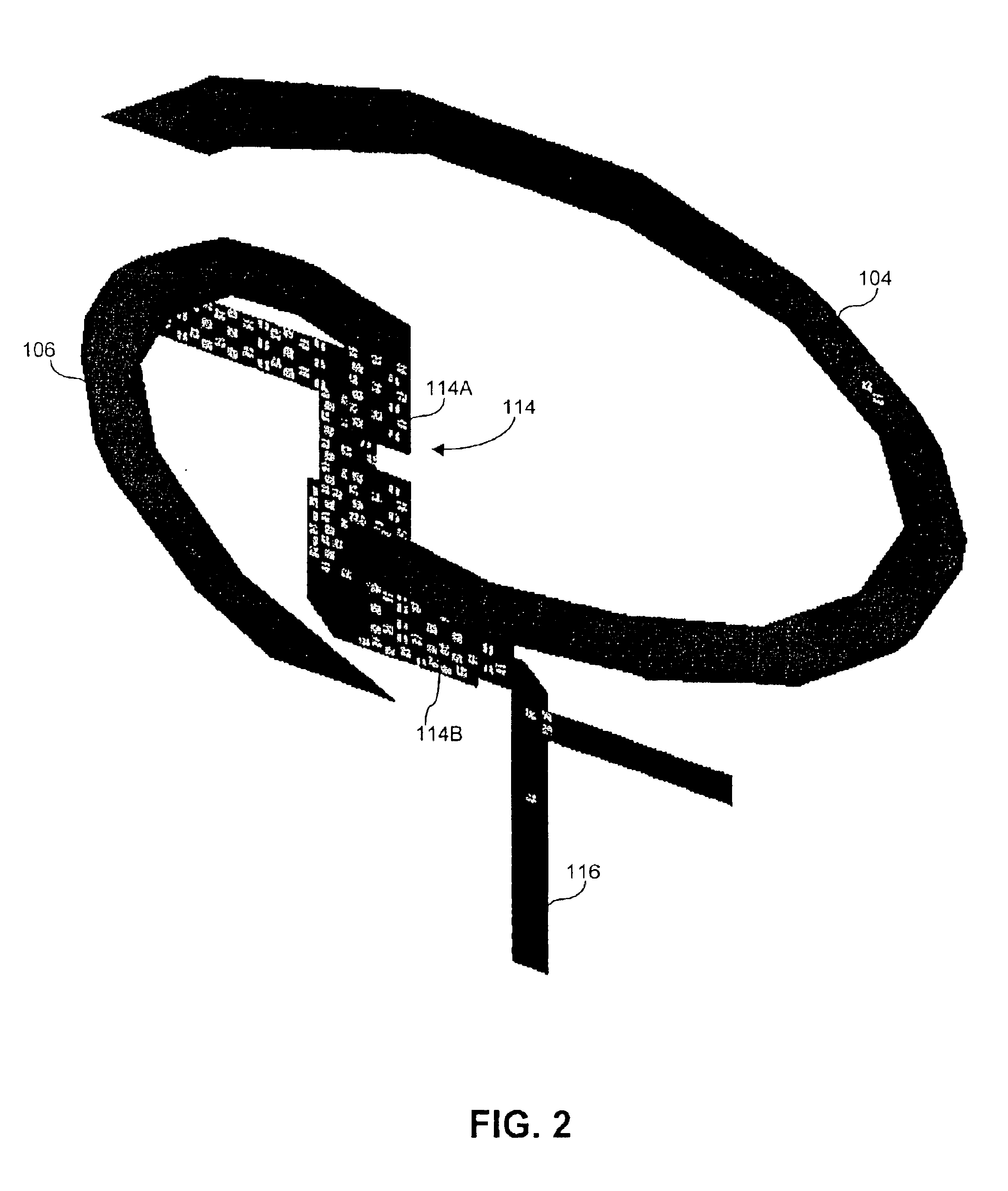
FIGS. 1-2 show a system 100 that includes an elongated spiral antenna 102 according to embodiments of the present invention. Elongated refers to antenna 102 being more expanded or stretched along an X-axis. Antenna 102 includes first 104 and second 106 spiral portions or arms (hereinafter, both are referred to as arms). It is to be appreciated, more or fewer arms can be used without departing from the scope of the invention. In the example shown, each arm 104, 106 has four turns, which form a contracted portion 108 and an expanded portion 110 of antenna 102. The distance 118 between adjacent arms 114, 116 in the expanded portion 110 is greater than the corresponding distance 120 in the contracted portion 108. It is to be appreciated any number of turns can be used, as is discussed below.

As best seen in FIG. 2, coupler 114 transmits an output signal from feed line 116 to antenna 102. Likewise, coupler 114 receives an input signal from antenna 102. It is to be ...


PUM


Abstract

A system includes a support device and an elongated spiral antenna coupled to the support device. The elongated spiral antenna has a contracted portion and an expanded portion. The expanded portion provides beam steering and directivity. The system also includes a feed line coupled to the elongated spiral antenna. A method for forming the elongated spiral antenna uses a predetermined formula to form arms of the elongated spiral antenna. The arms can be formed by printing the arms on a printed circuit board.

Description

BACKGROUND OF THE INVENTION1. Field of the InventionThe present invention is related to antennas positioned in compact environments that transmit and receive electromagnetic beams (“beams”) to and from various directions.2. Background ArtTraditionally, in order to receive or transmit beams to or in various directions an operator would either have to mechanically or manually move an antenna or build a large antenna array. These are costly in both time and materials. Also, as telecommunications devices become smaller and more mobile, these antennas cannot be configured to both be more compact and deliver the required functionality.Therefore, a need exists for a small antenna that is capable of being positioned in a mobile communications device, which also allows for transmission and reception of beams to and from various directions without requiring mechanical or manual moving of the antenna.BRIEF SUMMARY OF THE INVENTIONAn embodiment of the present invention provides a system includi...

Claims


Application Information

Patent Timeline
IPC IPC(8): H01Q1/38H01Q11/10H01Q1/24H01Q3/24H01Q25/00H01Q11/00
CPCH01Q1/241H01Q1/38H01Q25/002H01Q11/105H01Q3/24
Inventor ALEXOPOULOS, NICOLAOS G.DE FLAVIIS, FRANCOCASTANEDA, JESUS ALFONSO
Owner AVAGO TECH INT SALES PTE LTD
Why Eureka
Try Eureka