Automatic range adjustment techniques for stand-mountable bar code scanners

a bar code scanner and automatic range adjustment technology, applied in the field of optical bar code scanners, can solve the problems of scanner failure to detect and decode bar codes, and it is not possible to read any bar codes

Inactive Publication Date: 2005-03-08
METROLOGIC INSTR
View PDF25 Cites 221 Cited by
  • Summary
  • Abstract
  • Description
  • Claims
  • Application Information

AI Technical Summary

Problems solved by technology

Unless the object detection mechanism detects the presence of another object, the laser beam source will remain deactivated, and, in this state, it will not be possible to read any bar codes.
Problems arise if the scanner is mounted or remains in a position such that the object detection mechanism repeatedly detects the presence of a background object, over and over again, but at no time detects the absence of this object.
In such situations, the scanner will fail to detect and decode bar codes.

Method used


Image

  • Automatic range adjustment techniques for stand-mountable bar code scanners
  • Automatic range adjustment techniques for stand-mountable bar code scanners
  • Automatic range adjustment techniques for stand-mountable bar code scanners

Examples


Embodiment Construction

As stated above, the invention relates to stand-mountable bar code scanners that are equipped to operate in a long-range mode and a short range mode of object detection. Examples of such bar code scanners are disclosed in U.S. Pat. No. 5,340,971, issued on Aug. 23, 1994; U.S. Pat. No. 5,528,024, issued on Jun. 18, 1996; U.S. Pat. No. 5,525,789, issued on Jun. 11, 1996; U.S. Pat. No. 5,825,012 issued on Oct. 20, 1998; U.S. Pat. No. 5,886,337 issued on Mar. 23, 1999; U.S. Pat. No. 5,789,730, issued on Aug. 4, 1998; U.S. Pat. No. 5,837,989, issued on Nov. 17, 1998; and U.S. patent application Ser. No. 09 / 273,825 filed on Mar. 22, 1999. The disclosures of these issued U.S. Patents and patent application are incorporated by reference as if fully set forth herein.

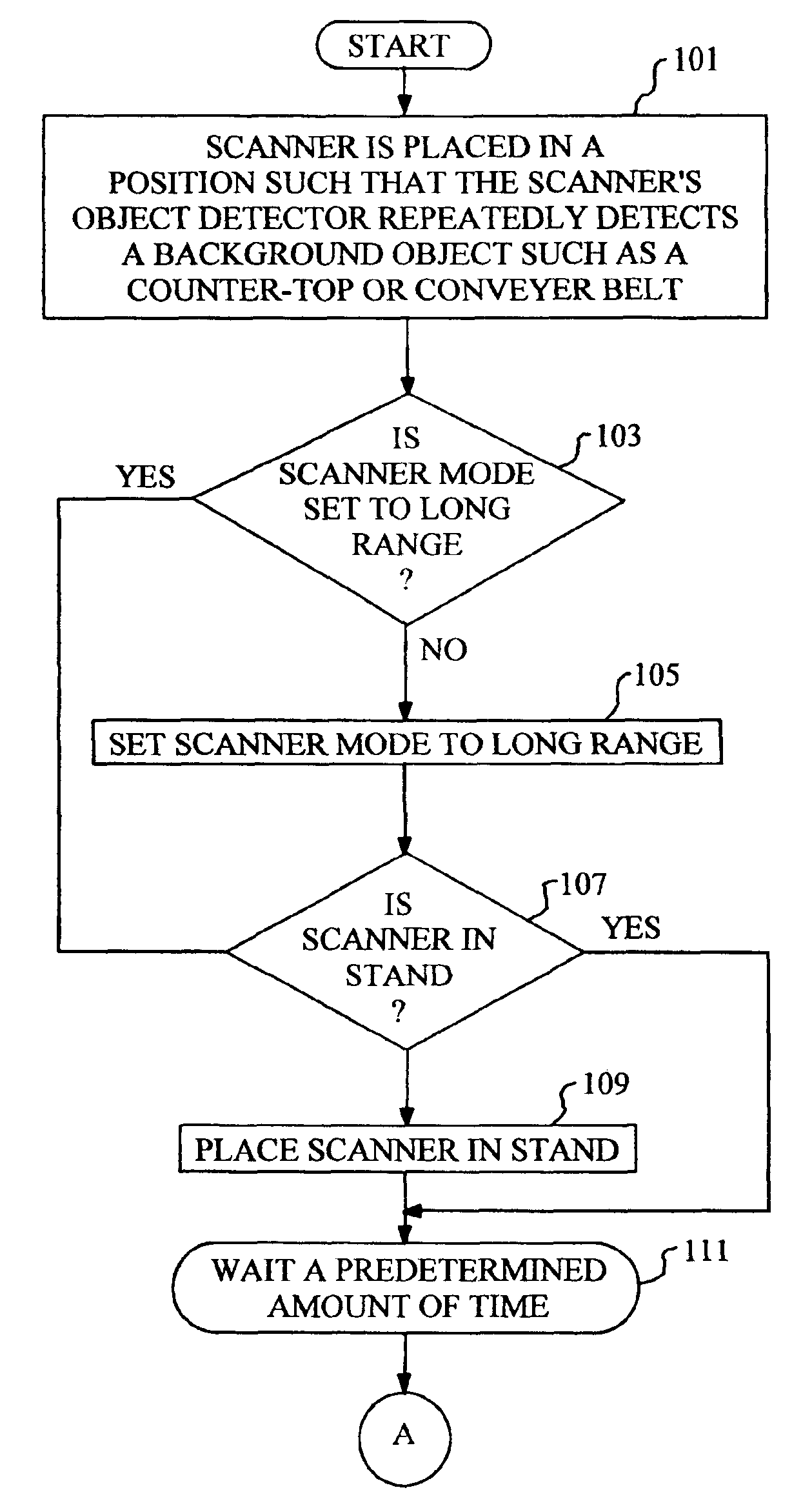
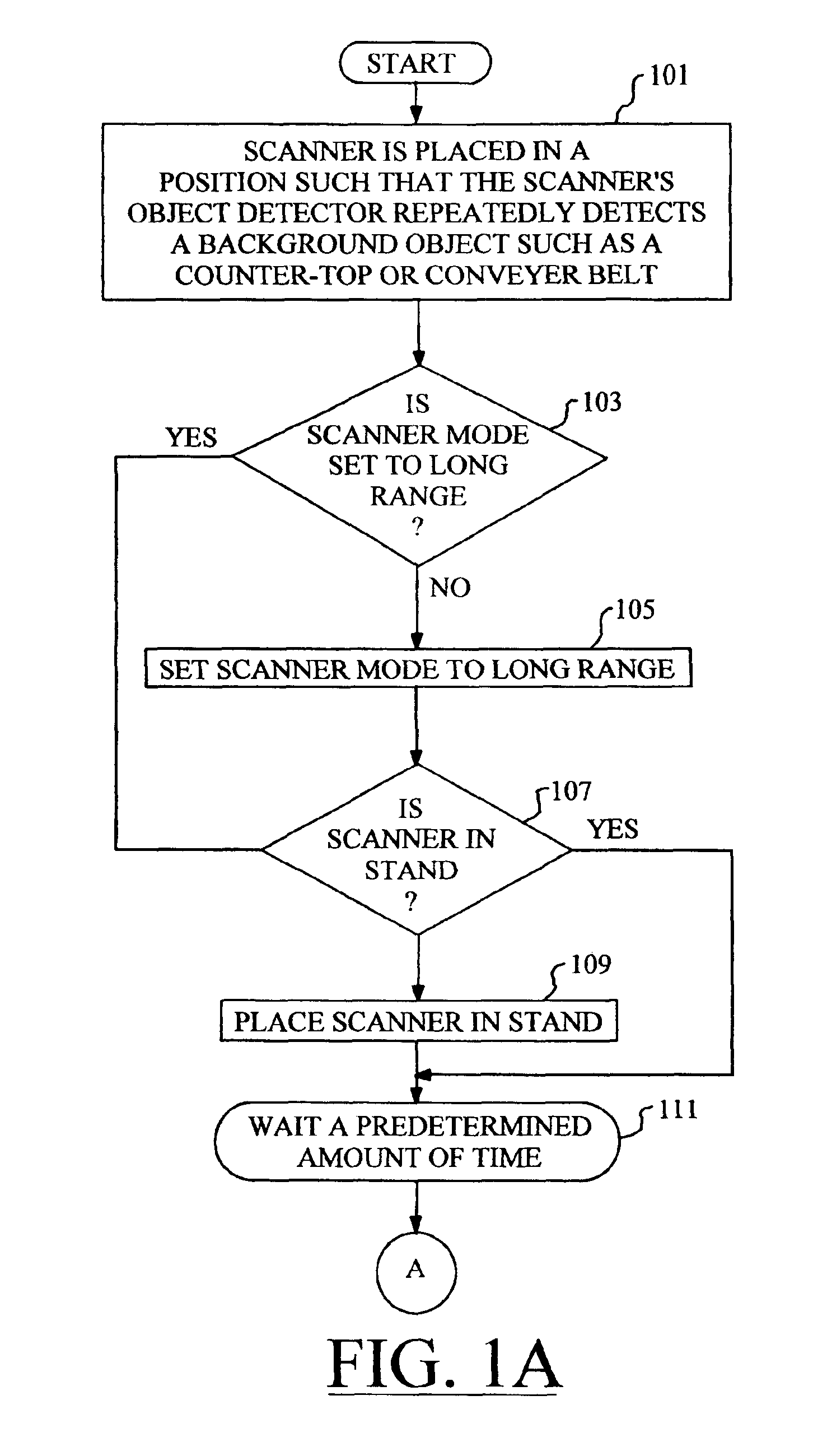
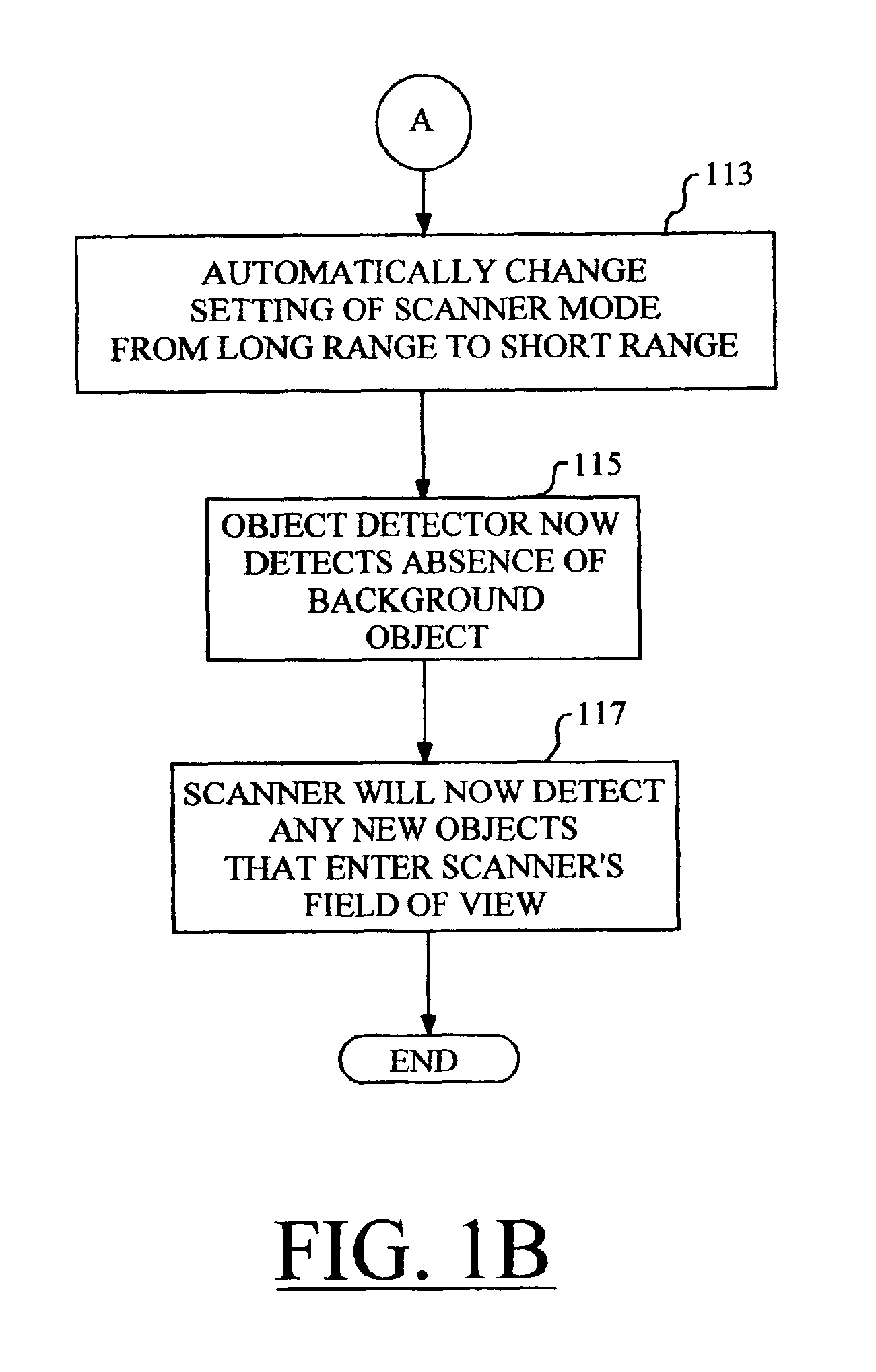
Refer now to FIGS. 1A and 1B, which together comprise a flowchart setting forth an operational sequence according to a preferred embodiment of the invention. The operational sequence commences at block 101, where a bar code scann...


PUM


Abstract

By automatically adjusting the object detection mechanism of a bar code scanner from a long range mode of operation to a short range mode of operation, the scanner will remain capable of detecting and decoding bar codes even if the object detection mechanism repeatedly detects the presence of a background object. The techniques of the present invention commence when the bar code scanner is placed in a position such that the scanner's object detection mechanism repeatedly detects a background object such as a counter top or conveyer belt. The object detection mechanism is set to the long range mode of operation if it is not already so set. In the case of a stand-mounted scanner, a test is performed to ascertain whether or not the scanner is in its stand, and the method will only proceed once the scanner is resting in the stand. Next, the scanner is programmed to wait for a predetermined amount of time, after which the operational mode of the object detection mechanism is changed from the long range mode to the short range mode. At this time, the object detection mechanism no longer detects the presence of the background object. The scanner will now detect any new objects that enter the field of view of the object detection mechanism, and attempt to read any bar codes which may be present

Description

1. FIELD OF THE INVENTIONThe invention relates generally to optical bar code scanners, and, more specifically, to stand-mountable bar code scanners that are equipped to operate in a long-range mode and a short range mode of object detection.2. BACKGROUND ARTMany existing optical bar code scanners utilize an object detection mechanism to determine if an object is in proximity to the optically transmissive window of the scanner. Illustratively, this object detection mechanism may be implemented using an infrared light source and an infrared detector. If an object is detected, the scanner will activate a laser beam source of a bar code detection and decoding mechanism so as to attempt a reading of one or more bar codes on the object. If, during this process, a bar code is not detected and decoded, the scanner will deactivate the laser beam source and wait for another object to enter the field of view of the object detection mechanism. Unless the object detection mechanism detects the p...

Claims


Application Information

Patent Timeline
Patent Type & Authority Patents(United States)
IPC IPC(8): G06K7/10
CPCG06K7/10851
Inventor HUDRICK, DONALD T.WILZ, SR., DAVID M.RUSSELL, GARRETT K.ROCKSTEIN, GEORGE B.SCHMIDT, MARK S.
Owner METROLOGIC INSTR
Why Eureka
Try Eureka