
Front suspension

a front suspension and suspension technology, applied in the field of front suspensions, can solve the problems and achieve the effect of increasing the roll stiffness of the vehicle and reducing the bending momen

Inactive Publication Date: 2005-03-15
DANA HEAVY VEHICLE SYSTEMS GROUP LLC
View PDF22 Cites 14 Cited by
  • Summary
  • Abstract
  • Description
  • Claims
  • Application Information

AI Technical Summary

Benefits of technology

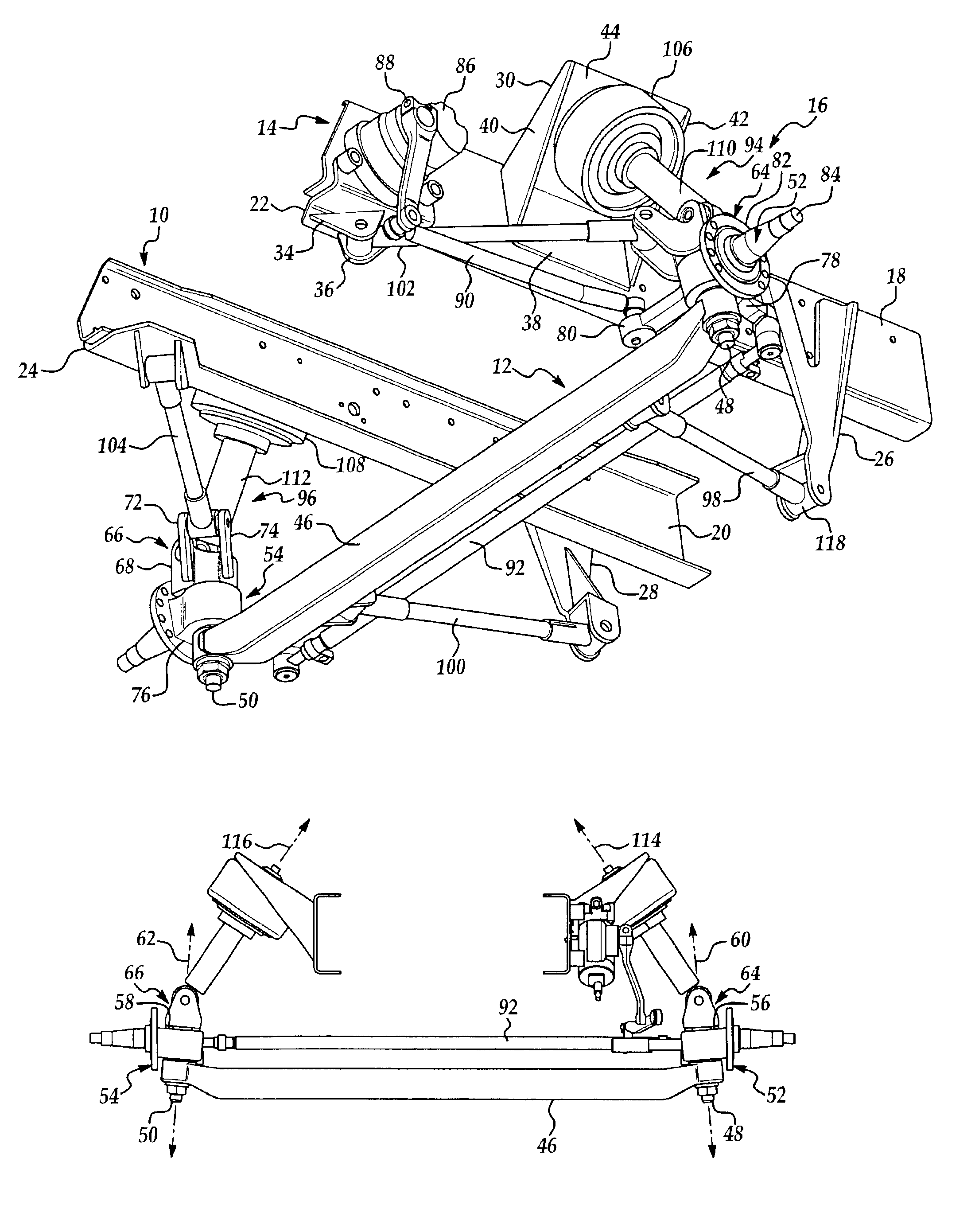
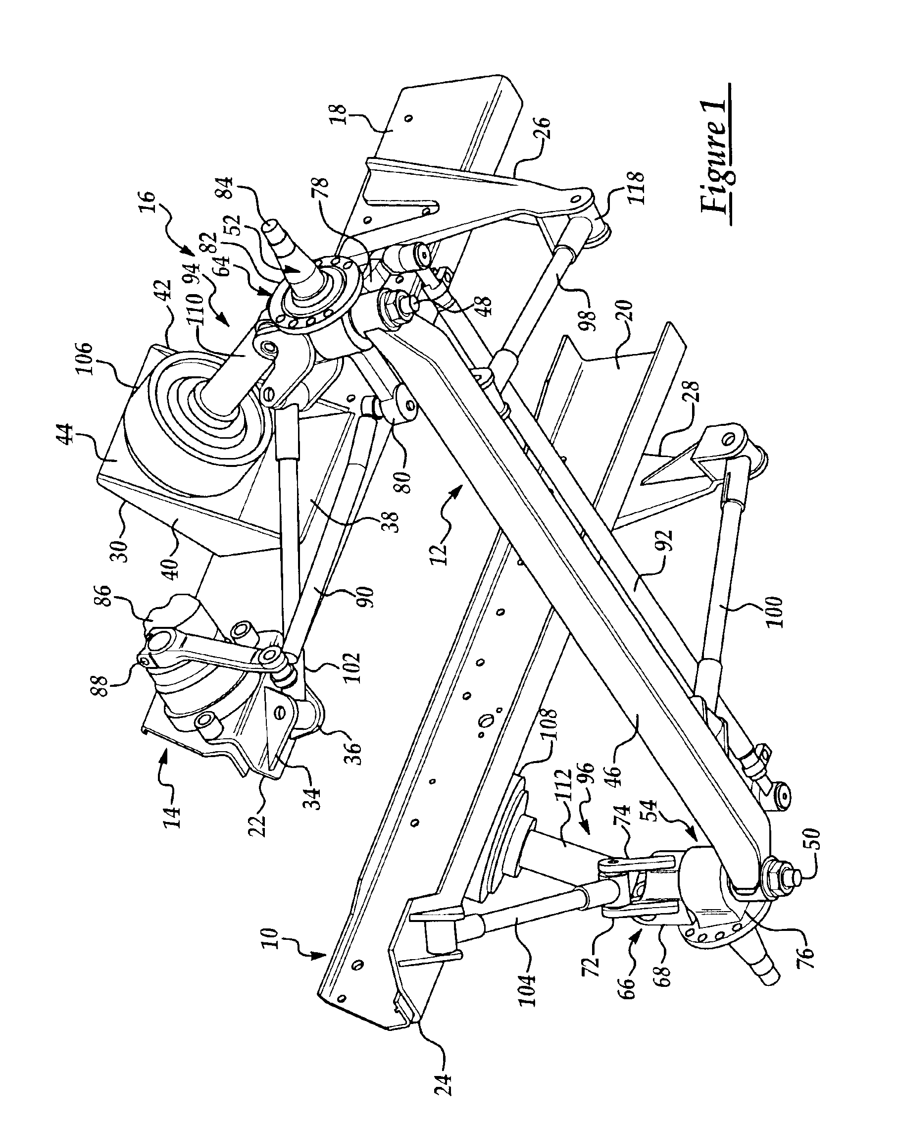
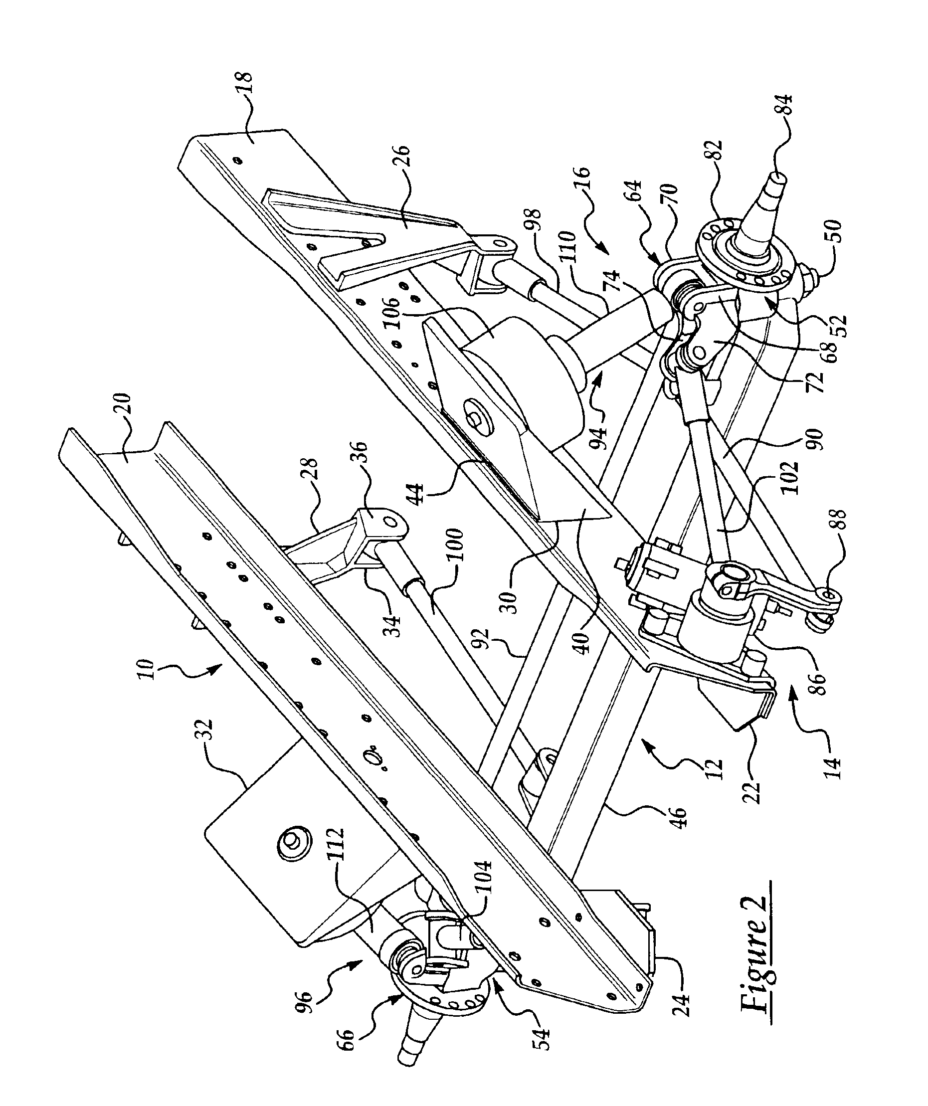
A suspension in accordance with the present invention is advantageous. The suspension moves one or more of the spring / shock absorber application and reaction points outboard of the vehicle frame rails with the application points proximate the wheels of the vehicle. As a result, the inventive suspension increases roll stiffness of the vehicle. Further, the inventive suspension reduces the bending moment induced on the axle beam allowing the use of a lighter and less expensive axle beam.

Problems solved by technology

As a result, the inventive suspension increases roll stiffness of the vehicle.

Method used


Image

  • Front suspension
  • Front suspension
  • Front suspension

Examples


Embodiment Construction

Referring now to the drawings wherein like reference numerals are used to identify identical components in the various views, FIGS. 1 and 2 illustrate a vehicle frame 10 having a steer axle assembly 12 coupled thereto by a steering assembly 14 and a suspension 16 in accordance with the present invention. In the illustrated embodiment, frame 10 and steer axle assembly 12 are adapted for use with a heavy truck. It should be understood, however, that the present invention may find application on a wide variety of vehicles.

Frame 10 is provided to support an engine (not shown), cab (not shown) and other components of a heavy truck. Frame 10 is conventional in the art and may be made from conventional metals and metal alloys such as steel. Frame 10 includes a pair of longitudinal rails 18, 20 extending in the direction of vehicle travel and in the longitudinal direction of the truck. Frame 10 may also include a plurality of cross-members (not shown) extending transversely between rails 18...


PUM


Abstract

A suspension for coupling a steer axle assembly to a vehicle frame is provided that moves one or more of the spring reaction points outboard to increase roll stiffness and enable the use of a lighter axle. In one embodiment of the invention, the suspension includes a spring coupled to the vehicle frame and a shock absorber having a first end coupled to the spring and a second end coupled to a component of the steer axle assembly, such as the kingpin, at a location outboard of a longitudinal frame rail of the vehicle frame.

Description

BACKGROUND OF THE INVENTION1. Field of the InventionThis invention relates to vehicle suspensions and, in particular, to a front suspension for coupling a steer axle assembly to a vehicle frame.2. Discussion of Related ArtA conventional vehicle includes a vehicle frame having a pair of longitudinally extending frame rails that support the vehicle engine and body. The frame is supported on a plurality of ground-engaging wheels that are disposed at opposite ends of a plurality of axles. The vehicle may contain, for example, a steer axle on which the wheels are steerable by the vehicle operator and a drive axle whose wheels are driven by the vehicle engine. Each of the axles are coupled to the vehicle frame through a suspension that dampens movements transmitted between the wheels and the vehicle frame.A conventional front suspension for a steer axle includes a spring disposed on each side of the vehicle. The springs extends vertically between the vehicle frame and spring seats formed ...

Claims


Application Information

Patent Timeline
Patent Type & Authority Patents(United States)
IPC IPC(8): B60G9/00
CPCB60G9/00B60G2200/30B60G2206/50B60G2204/129B60G2200/44
Inventor ZIECH, JAMES F.ZEBOLSKY, MICHAEL L.
Owner DANA HEAVY VEHICLE SYSTEMS GROUP LLC
Learn More