Electronically-controlled lateral stabilizer bar

A technology of stabilizer bar and stabilizer bar, which is applied in the interconnection system, suspension, transportation and packaging, etc. It can solve problems such as insufficient performance, hindering tires from touching the ground, and large roll when turning, so as to improve stability and comfort , The effect of preventing the loss of driving force and increasing the roll stiffness

Inactive Publication Date: 2017-12-08
合肥创智汽车技术开发有限公司
View PDF8 Cites 3 Cited by
  • Summary
  • Abstract
  • Description
  • Claims
  • Application Information

AI Technical Summary

Problems solved by technology

[0003] However, the stabilizer bar will affect the off-road performance of the vehicle. When driving in a straight line on a bad non-paved road, it is often encountered that the two coaxial wheels are at different heights. At this time, the stabilizer bar will prevent the tire from touching the ground. It even makes one side of the tire hang in the air, which greatly weakens the driving ability of the vehicle
In addition, if the designed stabilizer bar has a small stiffness, the straight-line driving comfort will be good, and the roll will be large when turning; on the contrary, if the designed stabilizer bar has a high stiffness, the straight-line driving comfort will be poor. The wheels on the other side will jump together, but the steering roll is better suppressed
Therefore, the contradiction between riding comfort and safety is difficult to balance, which makes the performance of the car decline.
[0004] Invention patent: CN103625238A discloses an electronically controlled stiffness-adjustable active lateral stabilizer, but it uses a planetary gear mechanism, resulting in a relatively cumbersome structure, and does not have the function of disconnecting the lateral stabilizer bar, so both cost and performance are expensive. There are deficiencies
These lead to its lack of performance

Method used


Image

  • Electronically-controlled lateral stabilizer bar
  • Electronically-controlled lateral stabilizer bar

Examples


Embodiment Construction

[0019] In order to make the technical means, creative features, goals and effects achieved by the present invention easy to understand, the present invention will be further elaborated below in conjunction with specific embodiments and accompanying drawings, but the following embodiments are only preferred embodiments of the present invention, not all . Based on the examples in the implementation manners, other examples obtained by those skilled in the art without making creative efforts all belong to the protection scope of the present invention.

[0020] Specific embodiments of the present invention will be described below in conjunction with the accompanying drawings.

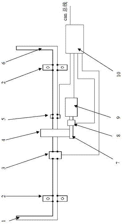
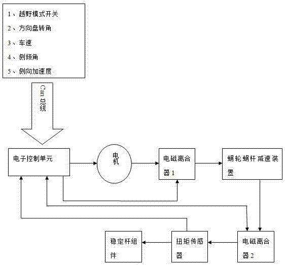
[0021] Such as figure 1 , 2 Shown, a specific embodiment of the present invention is as follows:

[0022] An electronically controlled stabilizer bar, one end of the left part 1 of the stabilizer bar assembly is connected to the suspension swing arm, the other end is fixed on the sub-frame through a rubbe...


PUM


Abstract

The invention relates to an electronically-controlled lateral stabilizer bar for an automobile, in particular to an electronically-controlled lateral stabilizer bar capable of being disconnected and with the rigidity capable of being adjusted actively. The electronically-controlled lateral stabilizer bar comprises a stabilizer bar body, a motor, a worm wheel and worm reduction device, an electromagnetic clutch, a torque sensor and an electronic control unit. The motor and the electromagnetic clutch are controlled to work through the electronic control unit, and the functions of disconnecting and lock-up of the lateral stabilizer bar, active adjusting of the rigidity of the lateral stabilizer bar and the like are achieved. According to the electronically-controlled lateral stabilizer bar, the design problems of the safety, the comfort and the passing ability of the lateral stabilizer bar can be effectively solved, meanwhile the structure is compact, the cost is moderate, and the electronically-controlled lateral stabilizer bar has a certain application and popularization value.

Description

technical field [0001] The invention relates to a lateral stabilizer bar for automobiles, in particular to an electronically controlled lateral stabilizer bar which can be disconnected and whose stiffness can be actively adjusted. Background technique [0002] The stabilizer bar is an auxiliary elastic element in the car suspension. Its function is to prevent the body from excessive lateral roll when turning, and try to keep the body as balanced as possible. The purpose is to reduce the degree of lateral roll of the car and improve ride comfort. Its working principle is that when the body only moves vertically, the suspension deformation on both sides is the same, and the stabilizer bar does not work. When the suspension on both sides jumps inconsistently, the stabilizer bar will be twisted, and the elastic force of the bar body will prevent the wheel from lifting, so that the body can be kept as balanced as possible and play a role in lateral stability. When the car turn...

Claims


Application Information

Patent Timeline
Patent Type & Authority Applications(China)
IPC IPC(8): B60G21/055
CPCB60G21/055B60G2204/8302
Inventor 吴兴泉赵雪梅
Owner 合肥创智汽车技术开发有限公司
Why Eureka
Try Eureka