Conveying apparatus

a technology of conveying apparatus and supporting surface, which is applied in the direction of conveyors, jigging conveyors, transportation and packaging, etc., can solve the problems of catastrophic failure, inability to manufacture the desired length, damage to the machine itself or the supporting surface, etc., and achieves the effect of reducing the cost of assembly and manufacturing

Inactive Publication Date: 2005-03-22
KII TEKU INC
View PDF29 Cites 36 Cited by
  • Summary
  • Abstract
  • Description
  • Claims
  • Application Information

AI Technical Summary

Benefits of technology

A further aspect of the present invention relates to a conveying apparatus which includes a supporting frame; an article transporting bed which is oriented in spaced relation relative to the supporting frame; a plurality of first beam springs mounted on the supporting frame and extending between the supporting frame and the article transporting bed to moveably support the article transporting bed in spaced relation relative to the supporting frame; a drive assembly mounted on the supporting frame and which has a plurality of second beam springs each having a first end which is mounted on the supporting frame, and an opposite second end, and a variable speed motor mounted on the second end of the second beam springs, and which rotates an eccentric mass to generate an oscillating force which is transmitted along a line of force which passes through the article transporting bed to cause the article transporting bed to reciprocate and have a predetermined stroke; a sensor borne by the conveying apparatus and which is configured to sense the stroke of the article transporting bed and transmit an output signal which substantially reflects the stroke of the article transporting bed; and a controller coupled in signal receiving relation relative to the sensor, and in speed controlling relation relative to the motor, and wherein the controller adjusts the speed of the motor based upon the output signal received from the sensor to substantially inhibit the article transporting bed from exceeding the predetermined stroke.

Problems solved by technology

In view of these performance characteristics, these types of conveyors are useful in various commercial environments where traditional vibratory conveyors would not be useful inasmuch as they would transmit too much vibratory energy into the supporting surface thereby potentially causing damage to the supporting surface or to the machine itself or further cannot be fabricated into the desired lengths which are useful in a given commercial environment.
It is reported in this patent that during these periods of transition, significant vibrational forces are transferred into the floor or ceiling supports which may result, on occasion, in catastrophic failures such as when a conveyor system becomes dislodged from its supports.
While this arrangement would appear satisfactory, at least on first analysis, this same arrangement is somewhat costly to manufacture and further includes a translating mass weighing several hundred pounds which creates a vibratory force which is transmitted substantially along a straight line, and which is reported to never match the natural frequency of the frame.

Method used


Image

  • Conveying apparatus
  • Conveying apparatus
  • Conveying apparatus

Examples


Embodiment Construction

This disclosure of the invention is submitted in furtherance of the constitutional purposes of the U.S. Patent Laws “to promote the progress of science and useful arts” (Article 1, Section 8).

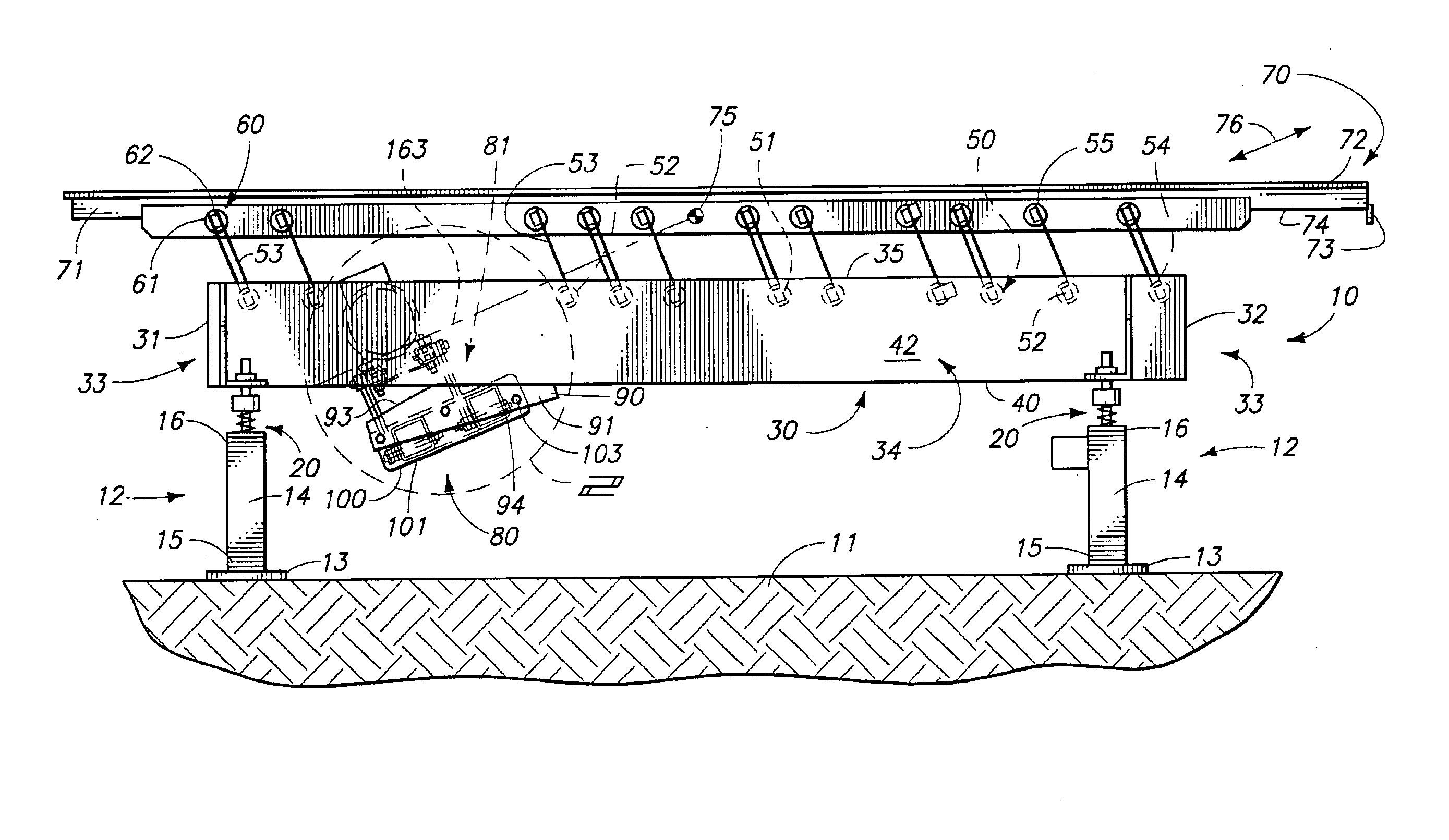
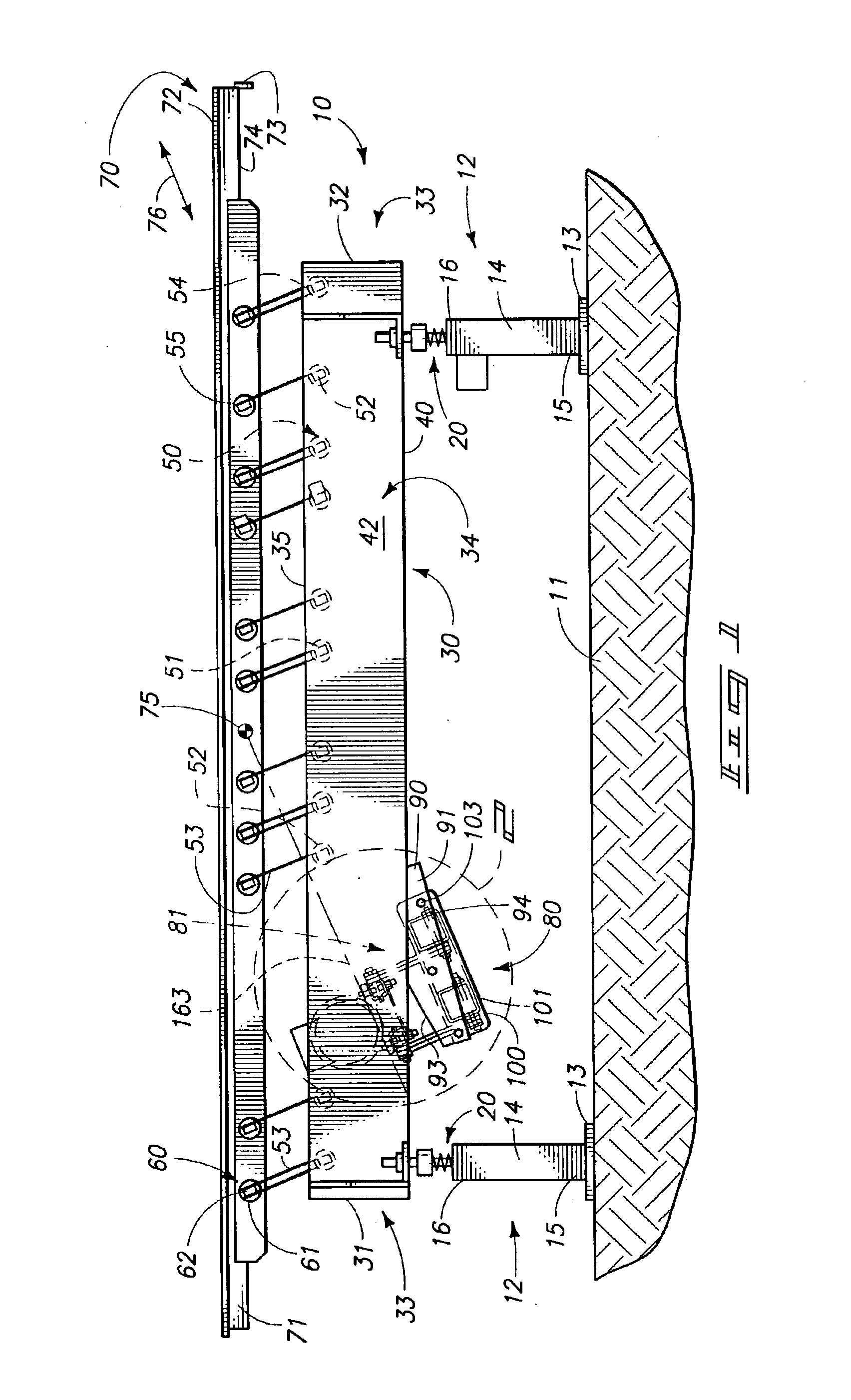
The conveying assembly of the present invention is generally indicated by the numeral 10 in FIGS. 1 and 3. The present conveying apparatus is an excited frame vibratory conveyor which is shown resting on the surface of the earth 11 by supporting legs which are generally indicated by the numeral 12. The supporting legs include a base member 13 which rests on the surface of the earth and a leg portion 14 which extends substantially normally upwardly a given distance therefrom. The leg portion 14 has a first end 15 which is affixed to the base member 13, and an opposite, distal, or second end 16 which is remote thereto. Mounted on the second end 16 of each of the supporting legs 12 is a vibration isolating spring assembly which is generally indicated by the numeral 20. Affixed to the vibration iso...


PUM


Abstract

A conveying apparatus is disclosed and which includes a supporting frame; an article transporting bed which is oriented in spaced relation relative to the supporting frame; a plurality of resilient supports mounted on both the supporting frame and the article transporting bed and which supports the article transporting bed in spaced relation relative to the supporting frame; and a drive assembly borne by the supporting frame and which provides an oscillating force having a plurality of components and which causes the article transporting bed to move reciprocally, and wherein the drive assembly amplifies the components of the oscillating force which are at a given angle relative to the resilient supports.

Description

TECHNICAL FIELDThe present invention relates to a conveying apparatus, and more specifically to an excited frame conveying apparatus having improved drive assemblies.BACKGROUND OF THE INVENTIONVibratory conveying systems of various designs are well known in the art. One form of vibratory conveying system is the excited frame conveyor. An example of such a vibratory conveyor is seen in U.S. Pat. No. 4,313,535 to Carmichael and which is incorporated by reference herein. Still further, an excited frame conveyor which has an operational frequency greater than the first natural structural frequency of the frame is disclosed in U.S. patent application Ser. No. 09 / 810,307. The teachings of this pending application are also incorporated by reference herein.Excited frame conveyors of these, and other similar designs, have provided many advantages over traditional vibratory conveyors inasmuch as these conveying systems are able to convey product efficiently, while simultaneously not transmitt...

Claims


Application Information

Patent Timeline
Patent Type & Authority Patents(United States)
IPC IPC(8): B65G27/10B65G27/20B65G27/32
CPCB65G27/20B65G27/32B65G2203/042B65G2203/0266
Inventor JONES, PETER T.
Owner KII TEKU INC
Why Eureka
Try Eureka