Connector door having overtravel stops

Inactive Publication Date: 2005-03-22
PANDUIT
View PDF31 Cites 31 Cited by
  • Summary
  • Abstract
  • Description
  • Claims
  • Application Information

AI Technical Summary

Benefits of technology

In yet another embodiment of the invention, there is provided a jack for receiving and connecting with a compatible plug, the plug including a depressible latch, the jack including a housing including a pair of opposed top and bottom walls, a pair of opposed side walls extending between the top and bottom walls, and a rear bulkhead, the top, bottom, side walls and the rear bulkhead substantially defining a chamber having a forwardly facing orifice through which the plug is insertable into and removable from the chamber, the rear bulkhead not being integrally formed with any of the top, bottom, and side walls, and a pivotable prebiased door having a torsional spring mounted thereto and having a closed position generally disposed over and flush with the orifice when the

Problems solved by technology

Such high performance demands augment the need to maintain a connection environment devoid of foreign debris that may directly interfere with electrical connections, or may indirectly diminish performance by eroding and degrading connective hardware over time.
Just as damage to an electrical contact or terminal may deteriorate the performance of an electrical connector, concern for the prospect of damage to a fiber end is justified because such damage can degrade the quality of the signal transmitted over the fiber optic connector.
As fiber ends are commonly pre-polished, such damage may particularly thwart an expensive effort to provide hardware capable of reliable, high-performance communication.
Likewise

Method used


Image

  • Connector door having overtravel stops
  • Connector door having overtravel stops
  • Connector door having overtravel stops

Examples


Example

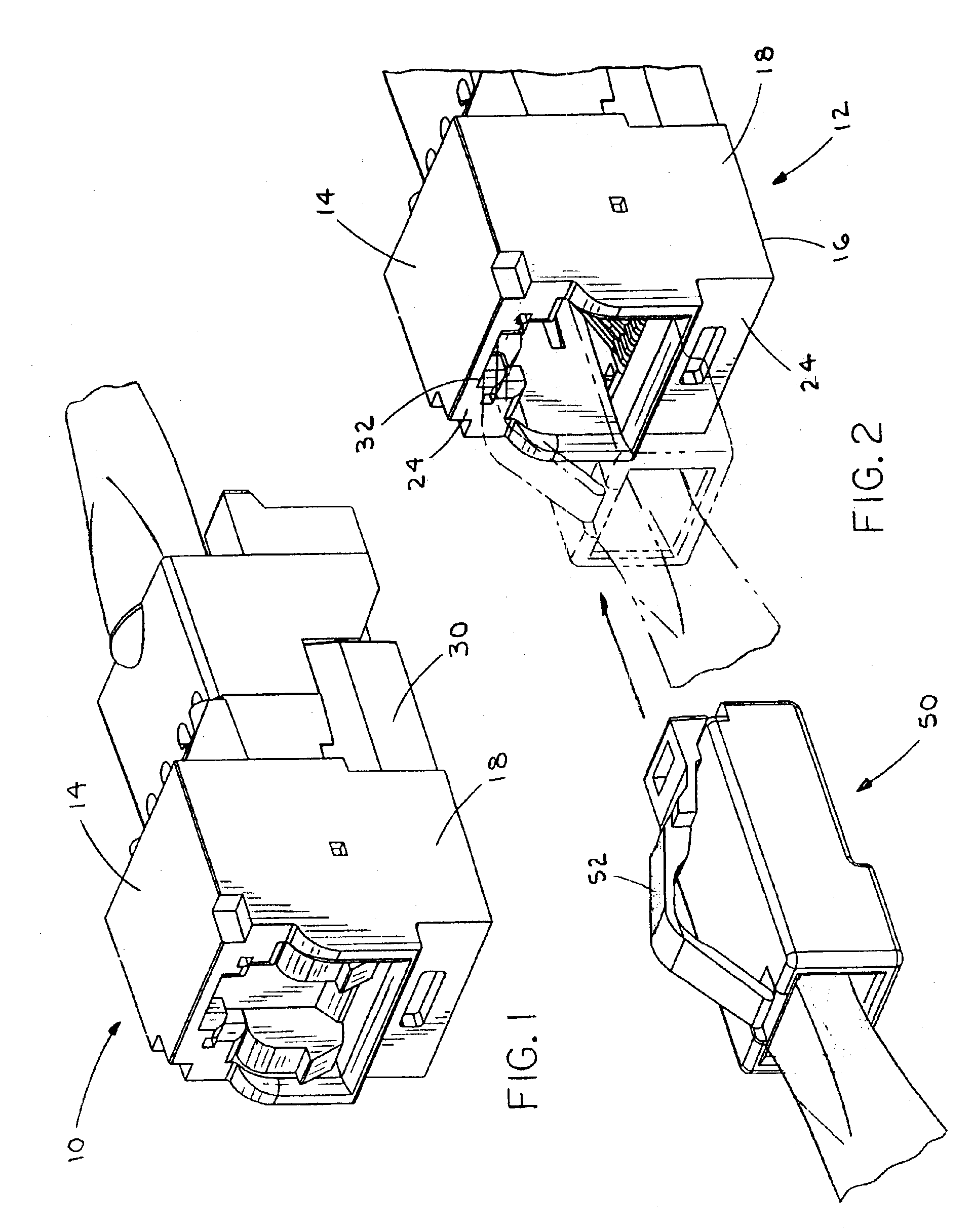
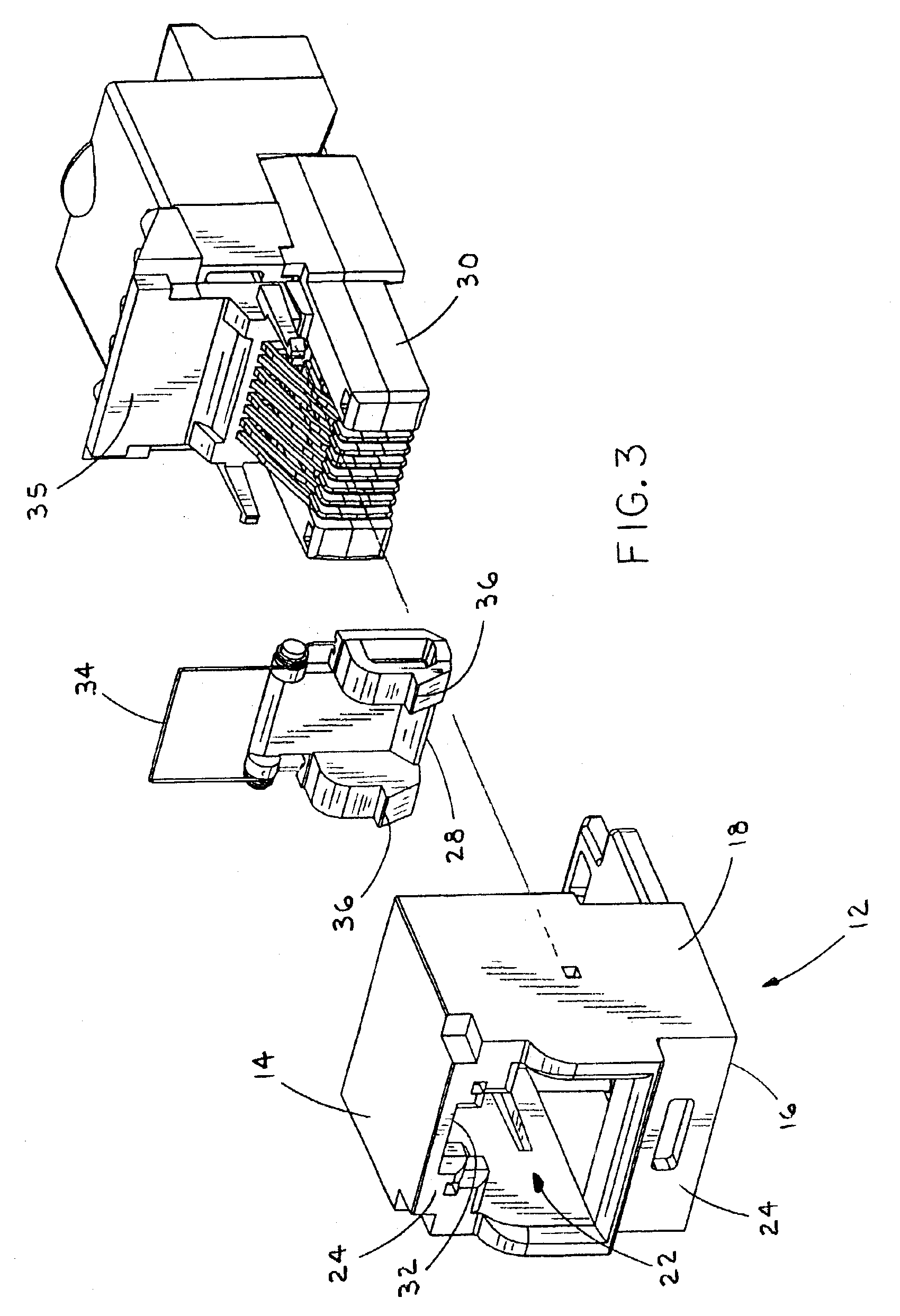
A preferred embodiment and an alternate preferred embodiment of the inventive connector are shown in the figures and described herein below. In the preferred embodiment, the connector takes the form of a TX-style jack 10 that includes a housing 12 having a plug-receiving chamber therein for receiving a cooperatively engageable TX-style plug 50 and thereby connecting with the plug, as seen in FIGS. 1 and 2. The inventive connector could alternatively take the form of a different type of electrical connector, or even a fiber optic connector.

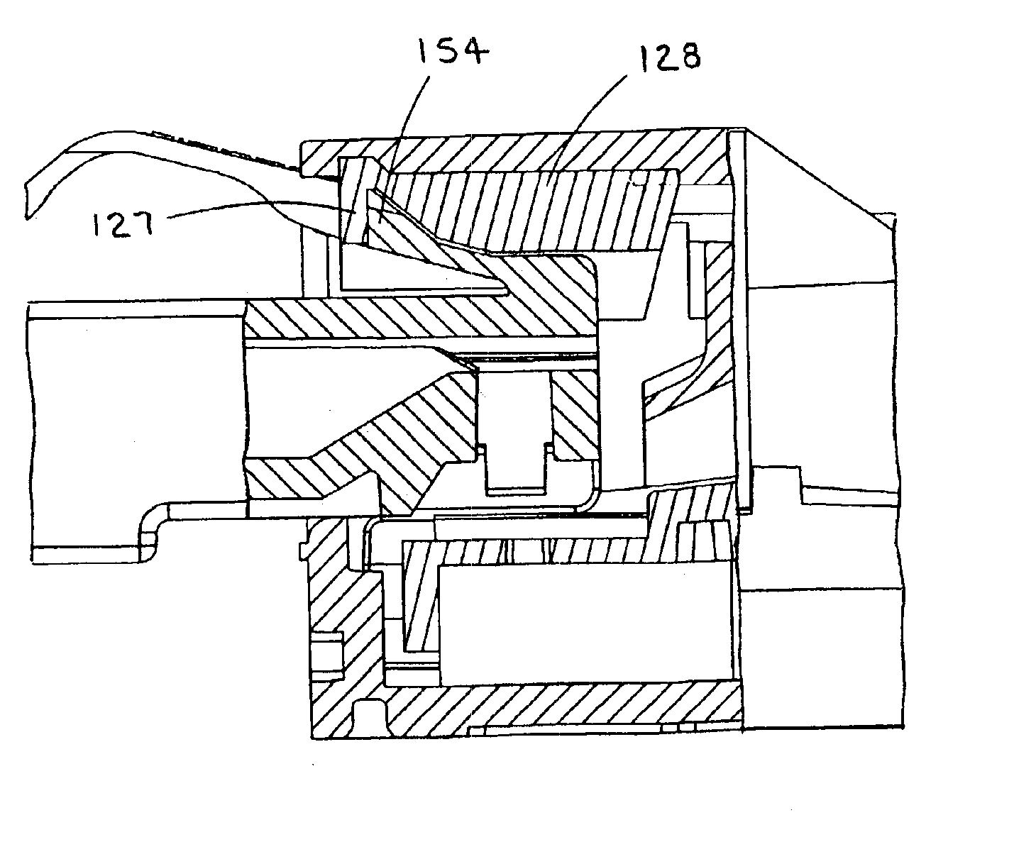
In a preferred embodiment, the housing 12 includes a top wall 14, a bottom wall 16, and a pair of side walls 18 that cooperatively define a plug-receiving chamber 20 therebetween. Though the front of the housing 12 includes an orifice 22 for receiving the appropriately configured plug 50 therethrough, the front may also preferably include a partial front wall 24 that extends inwardly from one or more of the top, bottom and side walls. The rear of t...


PUM


Abstract

A jack for receiving and connecting with a compatible plug, the jack including a housing having a plug-receiving chamber therein, the housing having an orifice through which the plug is insertable into and removable from the chamber, and a pivotable prebiased door having a closed position generally disposed over the orifice when the plug is not disposed within the chamber and an open position not generally disposed over the orifice when the plug is disposed within the chamber, the door including a projecting portion for limiting the extent of insertion of the plug into the chamber.

Description

BACKGROUND OF THE INVENTIONThe continuous demand for faster and higher quality signal transmission has led to connectors, such as those meeting Category 6 specifications, providing low crosstalk and high performance connectivity for electrical cabling. Such high performance demands augment the need to maintain a connection environment devoid of foreign debris that may directly interfere with electrical connections, or may indirectly diminish performance by eroding and degrading connective hardware over time.To inhibit the passage of foreign matter into or through a connector, some have tried using one or more protective shields disposed variously on or within the connector, particularly in fiber optic applications. Just as damage to an electrical contact or terminal may deteriorate the performance of an electrical connector, concern for the prospect of damage to a fiber end is justified because such damage can degrade the quality of the signal transmitted over the fiber optic connec...

Claims


Application Information

Patent Timeline
IPC IPC(8): H01R13/44H01R13/453G02B6/38H01R13/52
CPCH01R13/4536H01R24/62
Inventor CAVENEY, JACK E.
Owner PANDUIT
Why Eureka
Try Eureka