Pickup tool with variable position limiting and variable axis of operation
What is Al technical title?
Al technical title is built by PatSnap Al team. It summarizes the technical point description of the patent document.
a pick-up tool and variable position technology, applied in the field of hand tools, can solve the problems of affecting the use of the tool, the pressure on the object to be captured by the tool, and the inability of people to hold a long-term grasping power in their hands, so as to achieve the effect of easy modification
Inactive Publication Date: 2005-04-05
ARCMATE MFG
View PDF8 Cites 60 Cited by
Summary
Abstract
Description
Claims
Application Information
AI Technical Summary
This helps you quickly interpret patents by identifying the three key elements:
Problems solved by technology
Method used
Benefits of technology
The invention includes a non-symmetrical, curved, lockable element, preferably having a plurality of serrated indentations, uniquely positioned inside the tool body and arranged to move along a non-symmetrical, curvilinear path as an attached trigger is squeezed. A binding plate is also uniquely mounted inside the tool body for interacting with the lockable element and a pivotally-mounted actuator means held loosely in connection to the binding plate. When the actuator means is pivoted in one direction, it causes the binding plate to lock against the lockable element, preferably by sliding within the serrated indentations, thus, permitting the trigger to lock in a specific position, and permitting the attached moveable, pickup fingers to lock against an object. The tool can then be used to move the object without continuing to squeeze the trigger against the handle. The fingers' grasp against the object is easily unlocked when the trigger is slightly over-squeezed. The slight over-squeezing of the trigger causes the binding plate to unlock its position against the lockable bar, allowing the actuator, with the aid of a torque spring, to spring back to its original position, and allows the trigger to move back to its original position, and the fingers to release their grasp against the object and move back to their original position.
Accordingly, the main object of this invention is an elongated, pickup tool having an infinitely variable position limiting the fingers from fully opened to fully closed, and all positions in between. Other objects of the invention include an elongated, pickup tool that can easily be altered to have the fingers move along a plane that is different from the plane of the handle; a tool where all the position-related and finger-locking elements reside inside the tool itself; a tool where the locking elements can easily be positioned from a locking position to their original, unlocked position; a tool where the position of the locking fingers is infinitely variable; a tool where the rotation of the plane along which the fingers move can be accomplished without external tools; a tool where the elongated shaft is self-aligning; and a tool that may be used by men, women and children who are either right-handed or left-handed.
Problems solved by technology
In some instances, persons can use grabbers to retrieve bottles from high shelves, or crowded items from heavily stocked cabinets, however, many people do not have long term grasping power in their hands to retain a grip sufficient to grasp the item and continue to hold it while moving it from one place to another.
Such a lack of gripping power usually results in the item being dropped as it is moved.
In both of these devices, however, the pressure exerted against the object to be captured by the tool comes directly from the continuing pressure of the operator's hand squeezing the trigger.
These people are adversely affected by such a frozen design in the pickup tool.
Method used
Image
Click on the blue label to locate the original text in one second.
Reading with bidirectional positioning of images and text.
Examples
Embodiment Construction
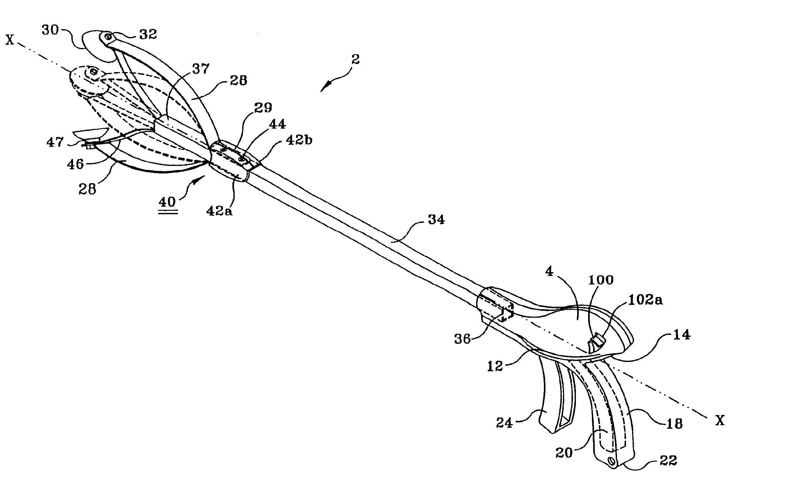
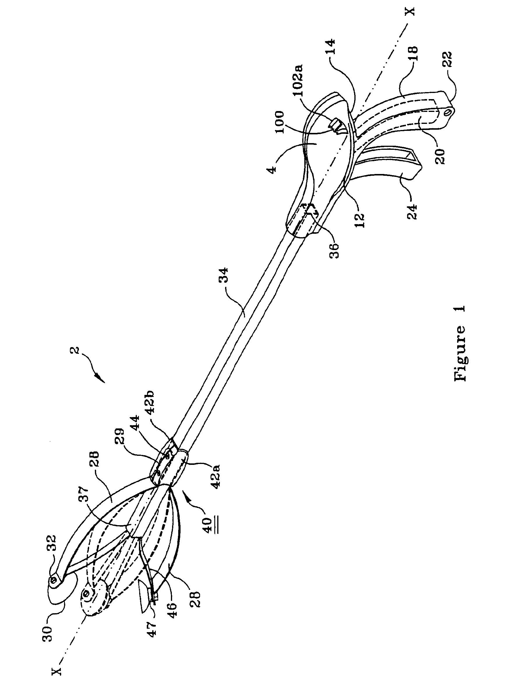
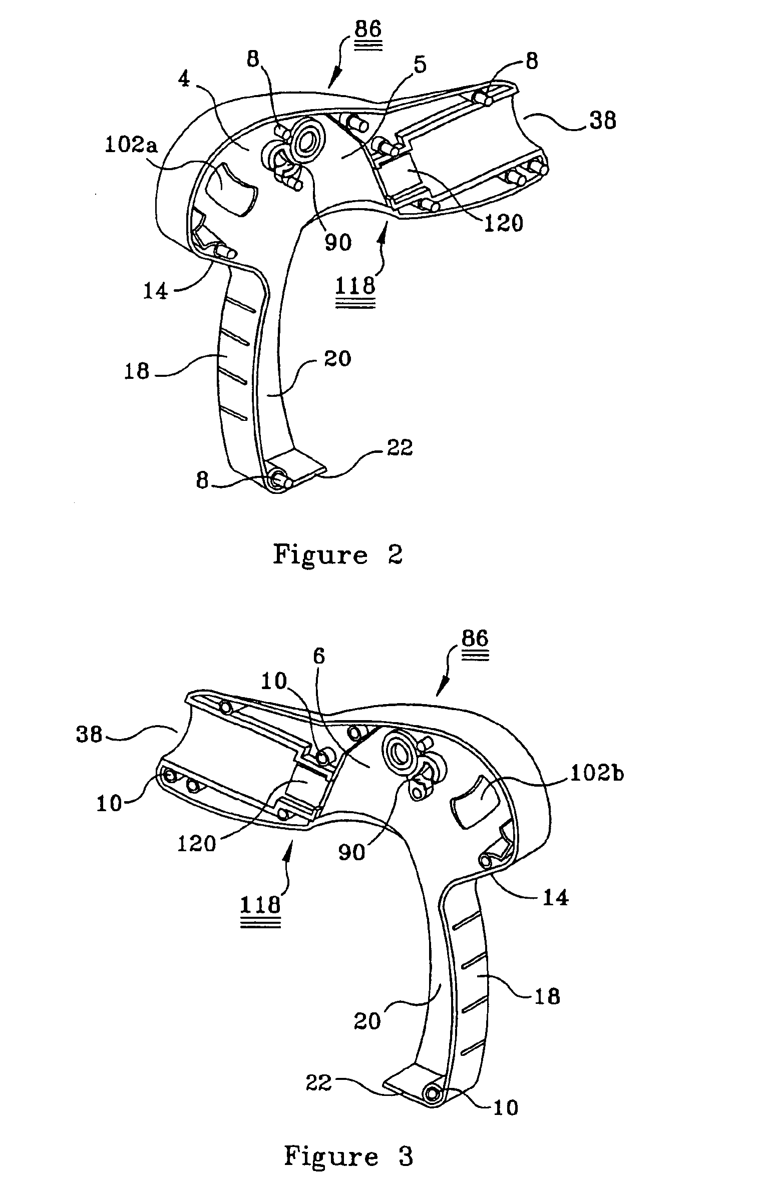
Turning now to the drawings where elements or limitations are identified with numbers and like elements or limitations are identified with like numbers throughout the ten figures, the preferred embodiment of the invention is shown in FIGS. 1-3 and shows a hand-held tool 2 for grasping items located at a distance from an operator. Tool 2 comprises a hollow body 4, preferably made of a light-weight plastic, and formed by at least two attachable side panels 5 and 6. A plurality of assembly pins 8, preferably molded thereon, and formed on the inside of side panel 5, is received by a plurality of aligned, assembly pin-receiving receptacles 10 on the inside of side panel 6, for attaching side panels 5 and 6 together. Body 4 has a pair of outwardly extending bulging ribs 12, one on each side panel, to provide a support area for the thumb of the operator when operator holds tool 2.
As shown in FIGS. 1, 2, and 3, a handle 18, preferably slender, for holding by either hand of the operator and ...
PUM
Abstract
A hand-held tool, for grasping items located at a distance from the operator, including a tool body, including a handle extending therefrom, for holding by the operator, and a moveable trigger operably arranged with the handle, at least one movable, pickup finger, for aid in grasping an item in response to squeezing the trigger, a first, elongated, rigid member, attached between the tool body and the at least one moveable finger, for holding the tool body and the at least one moveable finger, in a spaced-apart arrangement, a second, flexible member attached between the trigger and the at least one moveable finger, for moving the finger in response to movement of the trigger, a lockable element, a loosely-arranged binding plate, moveable by the thumb of the hand holding the handle, arranged for movement against the lockable element for permitting infinite locking positions of the at least one movable finger against the item grasped by the finger, and, a socket formed in the tool body for receiving the first, rigid, elongated member, the first, elongated, rigid member being adapted to be pulled out of the socket and be turned in any arrangement about the elongated, rigid member's central axis, for operating the attached at least one moveable finger, in any plane with the plane of the handle.
Description
BACKGROUND OF THE INVENTION1. Field of the InventionThis invention pertains to the field of hand tools. More particularly, it pertains to tools for undertaking manipulative operations spaced apart from the operator's hands, including picking up and moving objects from one place to another, with movable, pickup fingers. These tools are generally known as “reachers” or “grabbers.” This invention pertains to such tools having the novel property of infinitely variable position limiting of the moveable fingers and of having the ability of varying the plane of operation of the fingers.2. Description of the Prior ArtThere are situations where items are not within reach and physical barriers, such as limbs of trees, drain grates, furniture and the like, prevent one from grasping and / or retrieving or moving certain items. In these situations one often depends upon tools with grasping actions, spaced apart from the handle, to reach through the physical barriers. Such tools come in a variety o...
Claims
Application Information
Patent Timeline
Application Date:The date an application was filed.
Publication Date:The date a patent or application was officially published.
First Publication Date:The earliest publication date of a patent with the same application number.
Issue Date:Publication date of the patent grant document.
PCT Entry Date:The Entry date of PCT National Phase.
Estimated Expiry Date:The statutory expiry date of a patent right according to the Patent Law, and it is the longest term of protection that the patent right can achieve without the termination of the patent right due to other reasons(Term extension factor has been taken into account ).
Invalid Date:Actual expiry date is based on effective date or publication date of legal transaction data of invalid patent.