Shot calculator for billiards

a calculator and billiard technology, applied in the field of billiards, can solve the problems of not being able to play the game, requiring considerable practice, and being difficult to use, and the majority of learning aids that have been marketed, etc., to achieve the effect of facilitating the commercialization of the game, avoiding the use of devices, and avoiding the use of billiards

Inactive Publication Date: 2005-04-05
ELLIS CLYDE B
View PDF31 Cites 24 Cited by
  • Summary
  • Abstract
  • Description
  • Claims
  • Application Information

AI Technical Summary

Benefits of technology

Optionally, a full-size rail ruler which corresponds to the scale on the scaled playing table portion may be provided for placement on the rail/bumper of the actual billiards table co

Problems solved by technology

To achieve an acceptable level of proficiency in the game requires considerable practice.
As this can be frustrating and unfruitful for beginners, and at times for even the more advanced players, numerous learning aids have been devised over the years to assist players in developing and enhancing their proficiency in the game.
M

Method used


Image

  • Shot calculator for billiards
  • Shot calculator for billiards
  • Shot calculator for billiards

Examples


example 1

End Rail Bank Shot

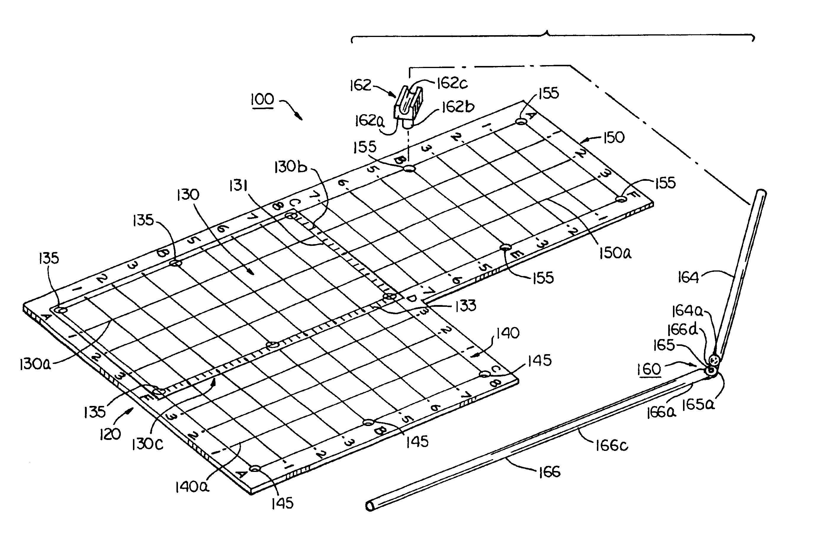
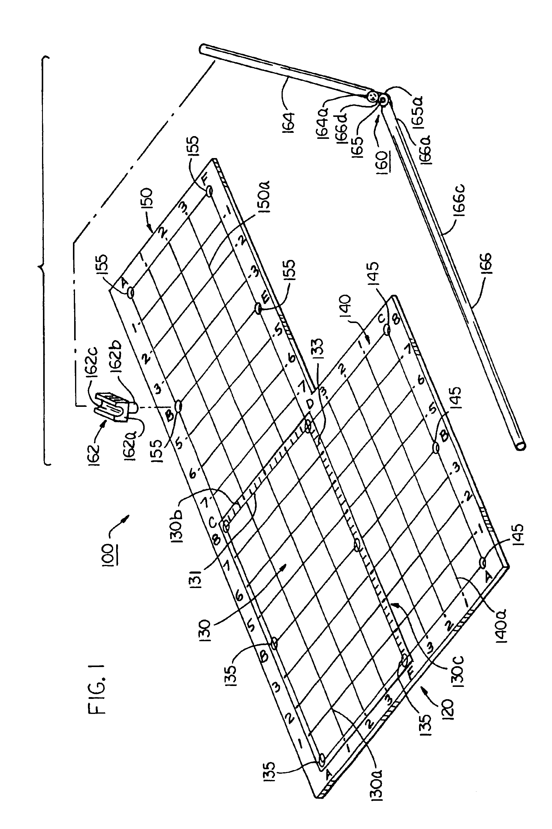
Turning now to FIG. 4, the first exemplary shot is an end rail bank shot to pocket ‘F’ on the scaled playing table portion 130, shown as position 410. The dowel 162b of the guide 162 is inserted into corresponding mirror pocket ‘F’, shown as position 420 on mirror table 150. End 164a of the object ball arm is then inserted into the slot 162c of the guide 162. The object ball arm 164 is then aligned with the object ball on the scaled playing table portion 130, shown as position 430. As shown in FIG. 4, the object ball position is approximately at coordinates X2, Y6⅛. This represents the position of the object ball on the actual billiards table. Note that the center of the object ball arm 164 crosses the scale 150 on the end rail at approximately X2⅜. This is the position that the actual object ball must strike in order to rebound into the corner pocket ‘F’, position 410. As further shown, the cue ball arm 166 is pivotally connected to the object ball arm 164 at the ...

example 2

End Rail Bank Shot

Turning now to FIG. 5, another example of an end rail bank shot is shown, whereby the desired pocket position is pocket ‘B’ (position 510). The dowel 162b of the guide 162 is inserted into corresponding pocket ‘B’, shown as position 520 on mirror table 150. End 164a of the object ball arm is then inserted into the slot 162c of the guide 162. The object ball arm 164 is then aligned with the object ball on the scaled playing table portion 130, shown as position 530. As shown in FIG. 5, the object ball position is approximately at coordinates X3⅜, Y7¼. Again, this represents the position of the object ball on the actual billiards table. Again, note that the center of the object ball arm 164 crosses the scale 150 on the end rail at approximately X2⅞, Y8. This is the rail position that the actual object ball must strike in order to rebound into the side pocket ‘B’, position 510. The cue ball arm 166 is pivotally connected to the object ball arm 164 at the pivot point 16...

example 3

Side Rail Bank Shot

Turning now to FIG. 6, the first exemplary side rail shot is shown whereby the desired pocket position is pocket ‘C’ (position 610) on the scaled playing table portion 130, is shown as position 610. The dowel 162b of the guide 162 is inserted into corresponding pocket ‘C’, shown as position 620 on mirror table 140. End 164a of the object ball arm is then inserted into the slot 162c of the guide 162. The object ball arm 164 is then aligned with the object ball on the scaled playing table portion 130, shown as position 630. As shown in FIG. 6, the object ball position is approximately at coordinates X3⅜, Y4½. This represents the position of the object ball on the actual billiards table. Note that the center of the object ball arm 164 crosses the scale 150 on the side rail at approximately X4⅞, Y5 position 640. This is the rail position that the actual object ball must strike in order to rebound into the corner pocket ‘C’, position 610. As further shown, the cue ball...


PUM


Abstract

A device for calculating where a cue ball must cause an object billiard ball to strike the bumper of a billiards table in order to drive the object ball into a selected pocket of the billiards table of the type having two opposed end rails and two opposed side rails. The device includes a plotting board and a guide. The plotting board comprises a scaled playing table portion and at least one scaled mirror table portion having pocket positions formed thereon, wherein the mirror table adjoins at least one of the opposed end rails or opposed side rails and is a mirror image of the playing table portion. The plotter comprises a guide and an object ball arm, the object ball arm having a pocket guide end and an object end. When the guide is placed over a selected pocket position on the mirror table portion and the object ball end of the object ball arm is aligned with the object ball on the scaled playing table and the pocket guide end is aligned with the guide over the selected pocket position, the object ball arm will cross the scaled playing table at a point where the object ball must strike the bumper of the billiards table.

Description

FIELD OF THE INVENTIONThe present invention relates to the game of billiards, and, more particularly to a handheld device and method for calculating bank and kick shots using a mirror-image plotting technique.BACKGROUND OF THE INVENTIONThe game of billiards, of which the game of pool is one particular type of game, is a well known game of skill which has been played for hundreds of years in some form or fashion. The game is played by striking a cue ball with a cue stick, causing the cue ball to collide with another ball (the object ball) so as to drive the object ball into a selected pocket on the playing surface. Players accomplish this by employing one of two different shots utilizing the rails / cushions of the playing table.When the cue ball is caused to strike the target ball directly, so that the target ball rebounds from a rail cushion into a selected pocket, the shot is referred to as a “bank” shot. If, however, the cue ball is caused to strike the rail first before subsequent...

Claims


Application Information

Patent Timeline
IPC IPC(8): A63D15/00
CPCA63D15/006
Inventor ELLIS, CLYDE B.
Owner ELLIS CLYDE B
Why Eureka
Try Eureka