
Position adjustable outlet box system

a technology of outlet box and adjustable position, which is applied in the installation of lighting conductors, substation/switching arrangement casings, and coupling device connections, etc., and can solve problems such as the inability to replace dry wall rings

Active Publication Date: 2005-04-05
PW IND
View PDF10 Cites 68 Cited by
  • Summary
  • Abstract
  • Description
  • Claims
  • Application Information

AI Technical Summary

Benefits of technology

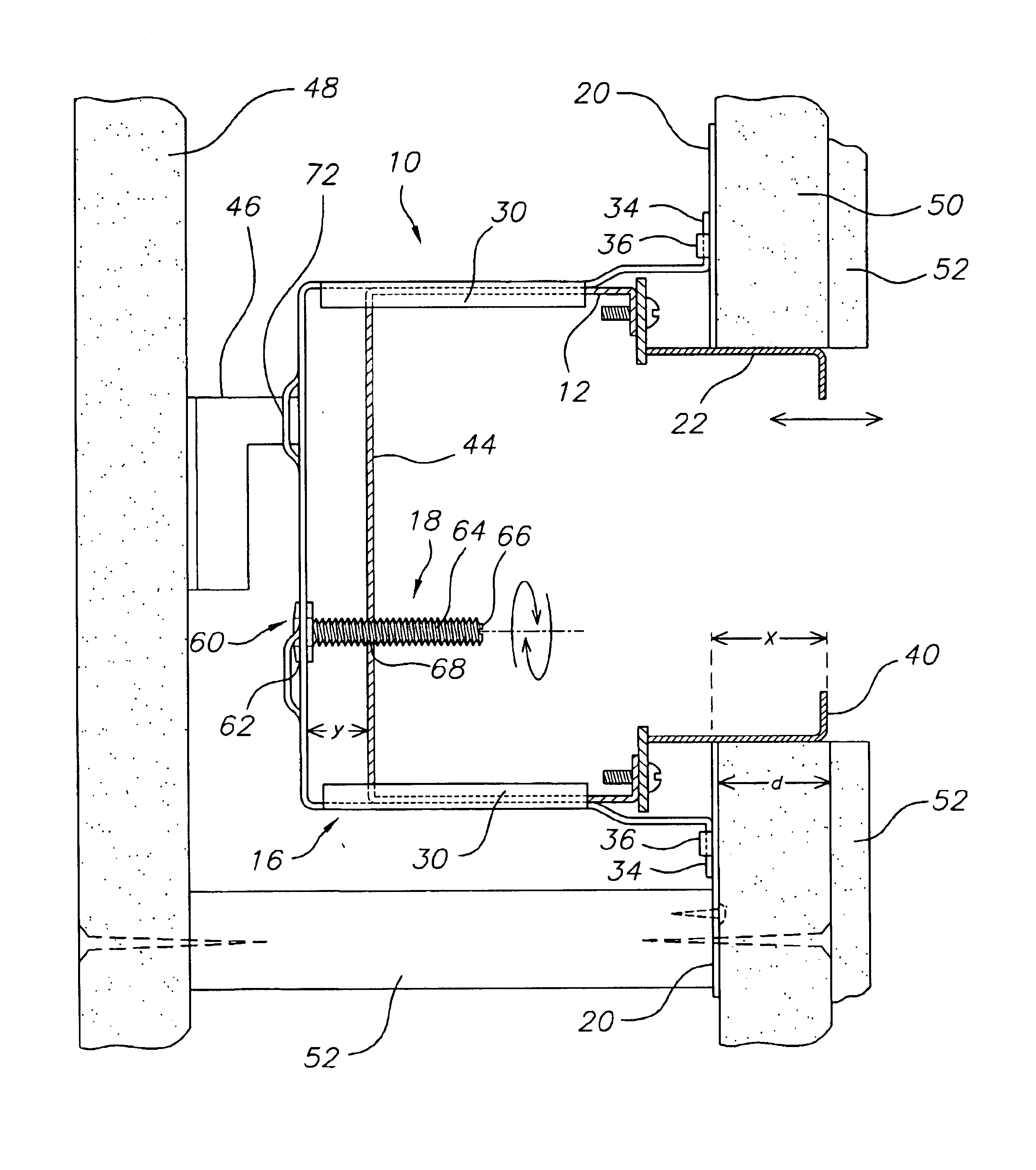
The position adjustable outlet box system has an outlet box cage which is attachable to a mounting bracket having an aperture formed therein. The outlet box cage is sized and dimensioned such that an outlet box will be able to slide inwardly and outwardly therefrom. The outlet box can be a conventional outlet box. A drywall ring with an extra long projecting neck portion, (e.g. about 4.0 cm or 1½ inches) is attached to the open face of the outlet box. The outlet box cage has support brackets which engage with a mounting plate, which mounting plate attaches to studs, joists, rafters, and the like. A depth adjustment mechanism is used to adjust the position of the outlet box within the outlet box cage. The depth adjustment mechanism can comprise a bolt, having a head which freely rotates relative to the outlet box cage, and a threaded shaft which threadably engages with a threaded hole in a back wall of the outlet box. The depth adjustment bolt can have an engagement portion to permit the depth adjustment bolt to be turned with a tool. This action of turning the bolt will cause the outlet box to be selectively moved inwardly and outwardly of the outlet box cage. In this manner, a top edge of the drywall ring can be made to be positioned at the ideal level relative to any wall covering material, even after the outlet box and its drywall ring is attached and a covering material is applied.

Problems solved by technology

However, this can be a big problem because once the wall material is covered over the conduit box, it is typically not possible to replace the dry wall ring without breaking away the covering material, e.g. if the builder or someone who comes back decides to later apply an extra layer of material.

Method used


Image

  • Position adjustable outlet box system
  • Position adjustable outlet box system
  • Position adjustable outlet box system

Examples


Embodiment Construction

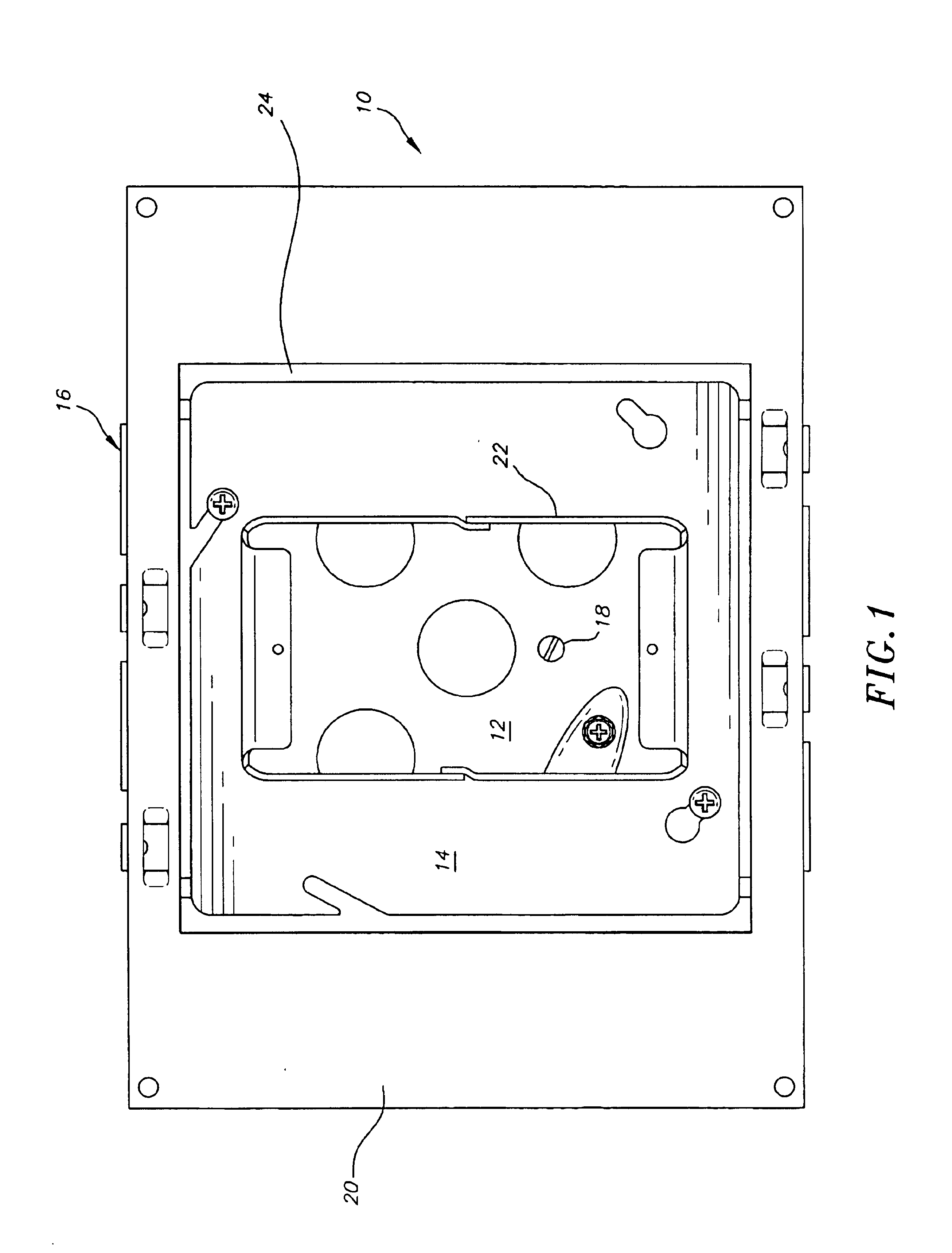
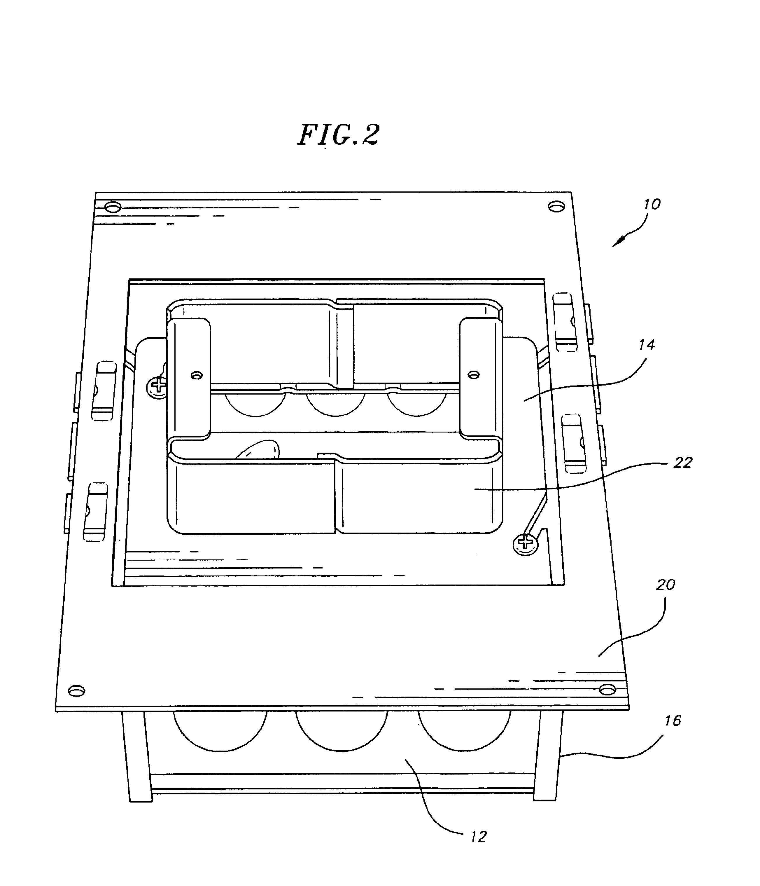
FIG. 1 is a front plan view of the position adjustable outlet box system 10 of the invention. The position adjustable outlet box system 10 includes an outlet box 12, a drywall ring 14 attached to an open front face of the outlet box, an outlet box cage 16 within which outlet box is slideably positioned, an adjustment bolt 18 which attaches between outlet box cage 16 and outlet box 12, and a mounting plate 20, which mounting plate 20 is suitable for attachment to a stud, joist, rafter, etc. (not shown) of a wall, ceiling or floor and the like. Drywall ring 14 has an extra long projecting neck portion 22 (e.g., at least about 2.5 cm (1 inch) and preferably about 4 cm (1½ inches) long or longer, up to about 5.1 cm (2 inches)), or as long as the realistically possible thickness of wall covering material which could ultimately be applied over the walls, ceiling, floor, etc. Mounting plate 20 has an aperture 24 formed therein which is sized to be at least as large as drywall ring 14. To p...


PUM


Abstract

A position adjustable outlet box system. The system has an outlet box cage, a mounting plate to which the outlet box cage is attached (having a outlet box aperture formed therein), an outlet box that is slideably retained in the outlet box cage, and a drywall ring having a projecting neck portion, which drywall ring is attachable to the outlet box. An adjustment mechanism is provided to permit adjustment of the depth position of the outlet box in the outlet box guide cage. The adjustment mechanism can includes a bolt that freely rotates along its axial axis (but does not move axially relative to the outlet box cage), a threaded shaft that screws into a threaded hole in a back wall of the outlet box and turning means that is accessible from within the outlet box to permit the outlet box's depth position within the cage to be adjusted as needed.

Description

FIELD OF THE INVENTIONThis invention relates to the field of outlet box mounting systems, and more particularly, to a position adjustable outlet box system suitable for mounting electrical devices, communication and electronic cabling, gases, and the like.BACKGROUND OF THE INVENTIONIn construction applications, electrical devices such as switches and plug outlets are mounted within boxes which themselves are retained within walls, floors and ceilings with power supply conduits supplied to the box and to the electrical device contained therein. Outlet boxes are also used for mounting other devices such as communication cabling including optical communication, co-axial cables, twisted pair of cables and the like. Furthermore, outlet boxes can also be used to contain various valve and control devices such as in hospitals where various gases such as oxygen can be supplied in wall or in floor applications. Vacuum supply can also be provided to such outlet boxes. In typical construction a...

Claims


Application Information

Patent Timeline
IPC IPC(8): H02G3/12H01H9/02
CPCH02G3/123H01H9/0207
Inventor PETAK, RANDYSHAW, JEFFREY
Owner PW IND
Learn More