Hydrostatic release mechanism

a technology of hydraulic release mechanism and floating emergency equipment, which is applied in the direction of floating buildings, special-purpose vessels, transportation and packaging, etc., can solve the problems of not being able to release all floating emergency equipment on a vessel in time, and none of the known prior art discloses the combination

Inactive Publication Date: 2005-04-12
C M HAMMAR
View PDF15 Cites 21 Cited by
  • Summary
  • Abstract
  • Description
  • Claims
  • Application Information

AI Technical Summary

Problems solved by technology

However, when the crew finds itself in a rapid sinking situation caused by, for example, when the structural integrity of the watercraft is seriously compromised via a collision with another vessel or a reef, there may not be enough time to release all of the floating emergency equipment on a vessel.
In such situations, the crew may find itself in the water with needed life rafts and emergency radio beacons still attached to the now submerged vessel.
None of the known prior art disclose the combination set forth herein.

Method used


Image

  • Hydrostatic release mechanism
  • Hydrostatic release mechanism
  • Hydrostatic release mechanism

Examples


Embodiment Construction

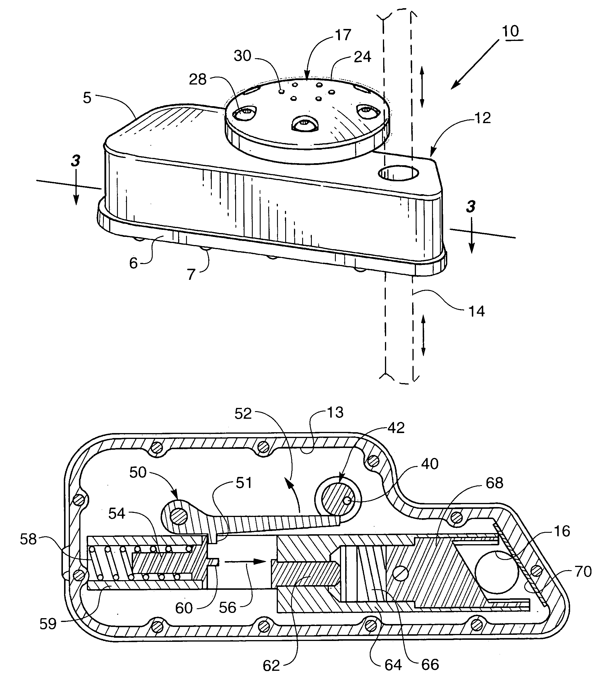
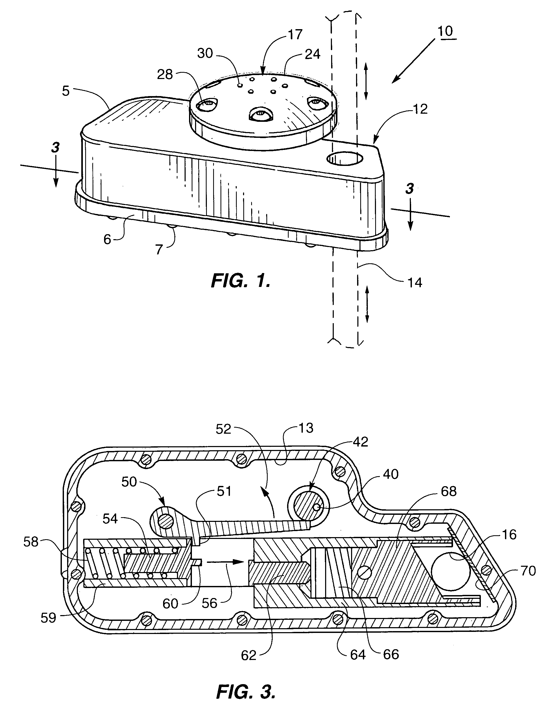
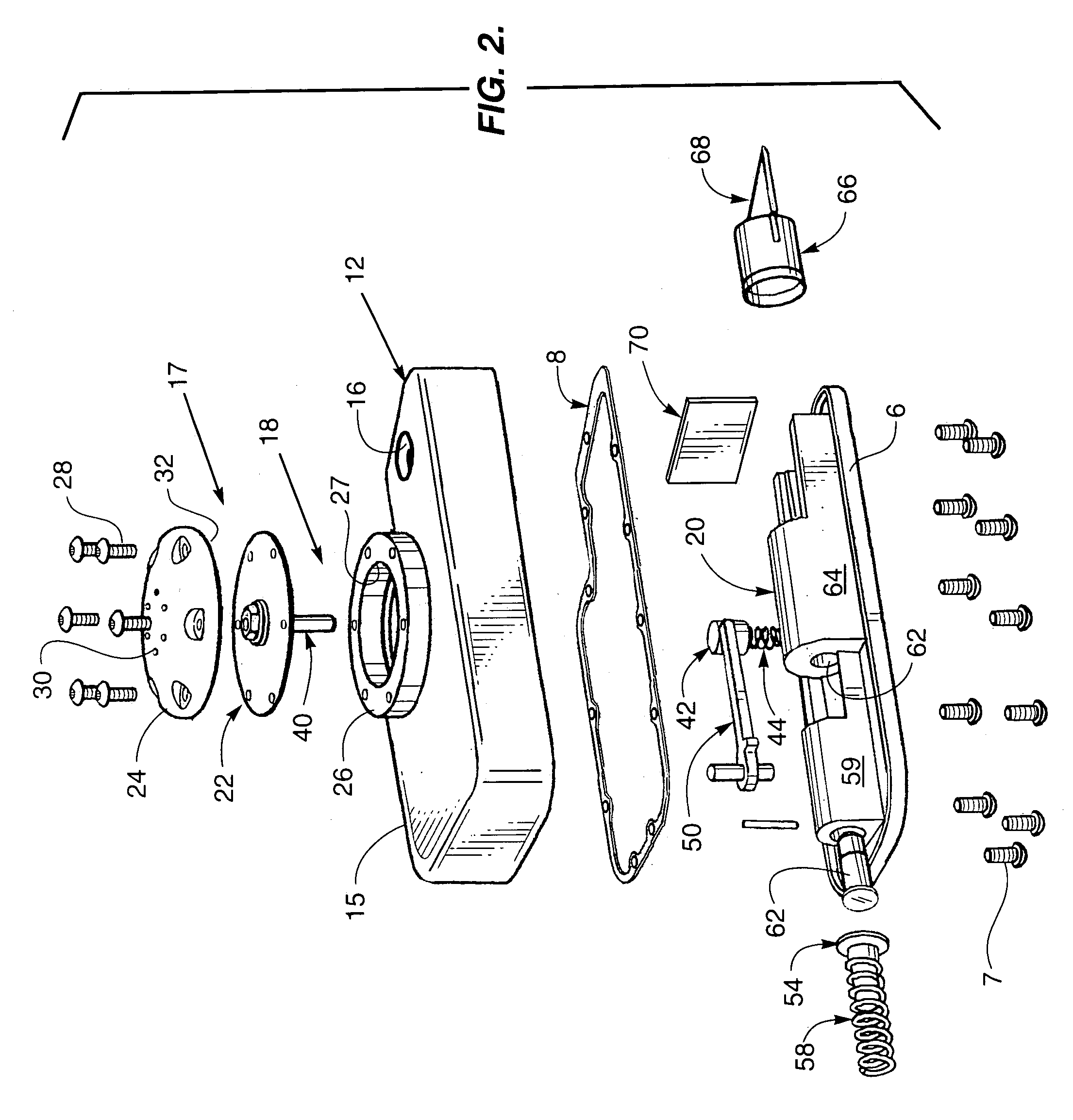
Referring more particularly to the drawings by characters of reference, FIGS. 1–3 disclose combinations of features which constitute the components of a hydrostatic release mechanism 10 of the present invention. Hydrostatic release mechanism 10 comprises a depth sensor 17 mounted to a sealed housing 12. In the illustrated embodiment, housing 12 comprises an upper portion 5 joined to a lower portion 6 by a plurality of bolts 7 thereby forming an interior volume 13. Those skilled in the art will recognize that other methods of joining are applicable to the present invention, including, but not limited to, ultrasonic welding.

A gasket 8 is captured between the peripheries of upper portion 5 and lower portion 6 to provide a seal between ambient conditions on the exterior of said housing and interior volume 13. Sealed housing 12 further provides a tunnel 16 extending through housing 12 which is adapted to receive a rope or tether 14 therein. Tunnel 16 is a continuous cylinder which is pre...


PUM


Abstract

A hydrostatic release mechanism is provided which comprises a sealed housing having an interior volume and a tunnel adapted to receive a tether extending therethrough. A depth sensor is mounted to the sealed housing and has a diaphragm covering an opening between the interior volume and the ambient conditions. A trigger is contained within the sealed housing and is operably connected to the diaphragm and a firing mechanism. The firing mechanism is actuated by movement of the trigger in response to inward movement of the diaphragm when the pressure on the diaphragm exceeds a predetermined force. The firing mechanism includes a piston having a blade which moves in response to the expanding gases from a pyrotechnic cartridge and passes through the tunnel thereby severing the tether extending therethrough.

Description

TECHNICAL FIELDThis invention relates generally to the field of hydrostatic release mechanisms, and, more particularly, to hydrostatic release mechanism which is designed to sever a tether securing a floating device from a watercraft when the watercraft is submerged to a predetermined depth.BACKGROUND OF THE INVENTIONFloating devices such as emergency radio beacons or life rafts are normally secured to a watercraft by tethers when not in use. As is well known, such life rafts are designed for use by the crew of said watercraft in an emergency. However, when the crew finds itself in a rapid sinking situation caused by, for example, when the structural integrity of the watercraft is seriously compromised via a collision with another vessel or a reef, there may not be enough time to release all of the floating emergency equipment on a vessel. Other rapid sinking scenarios include, but are not limited to, explosions, fire, storms and the like. In such situations, the crew may find itsel...

Claims


Application Information

Patent Timeline
Patent Type & Authority Patents(United States)
IPC IPC(8): B63B23/58B63B21/00B63B21/04B63B23/00B63C9/19
CPCB63B23/58B63B21/04
Inventor KOHUTH, KERRY R.
Owner C M HAMMAR
Why Eureka
Try Eureka