Computed tomography system with integrated scatter detectors

Inactive Publication Date: 2005-04-12
GE MEDICAL SYST GLOBAL TECH CO LLC
View PDF16 Cites 75 Cited by
  • Summary
  • Abstract
  • Description
  • Claims
  • Application Information

AI Technical Summary

Benefits of technology

One advantage of the present invention is that it generates an increased amount of information from a scanned object without the need for increased dosage or an increased number of scans.
Additional advantages and features of the pre

Problems solved by technology

A disadvantage of the aforementioned system is that acquiring further information requires either an increased dose of x-rays or an increased number of x-ray scans.
A further disadvantage of the aforementioned system is that back-scat

Method used


Image

  • Computed tomography system with integrated scatter detectors
  • Computed tomography system with integrated scatter detectors
  • Computed tomography system with integrated scatter detectors

Examples


Example

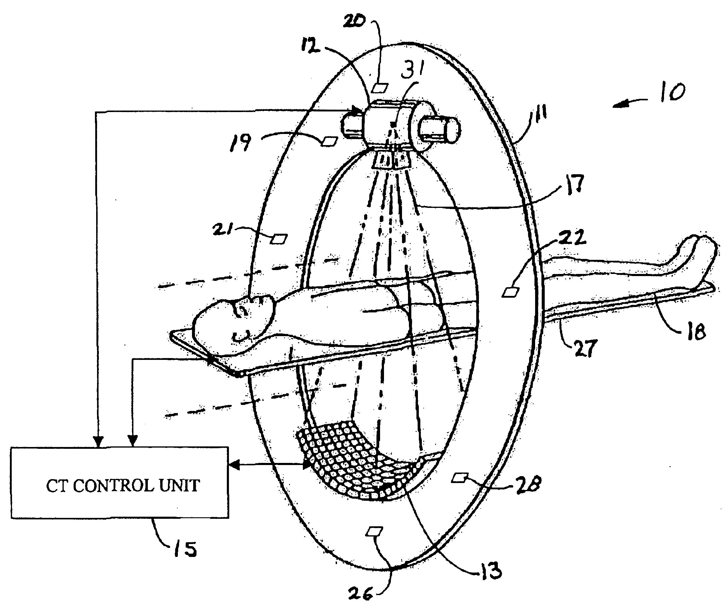
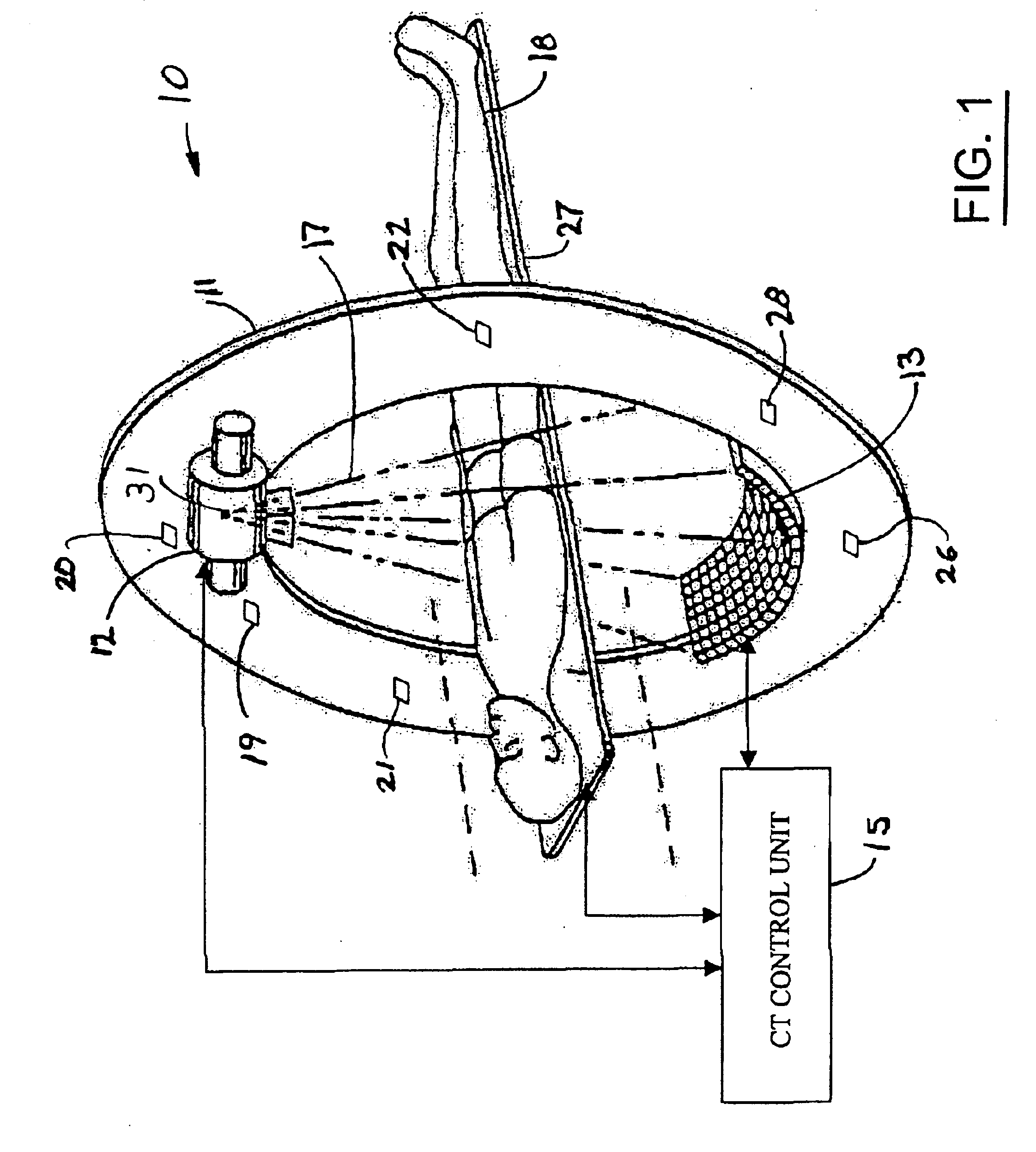
The present invention is illustrated with respect to a Computed Tomography (CT) scanning system 10, particularly suited to the medical field. The present invention is, however, applicable to various other uses that may require CT scanning, as will be understood by one skilled in the art.

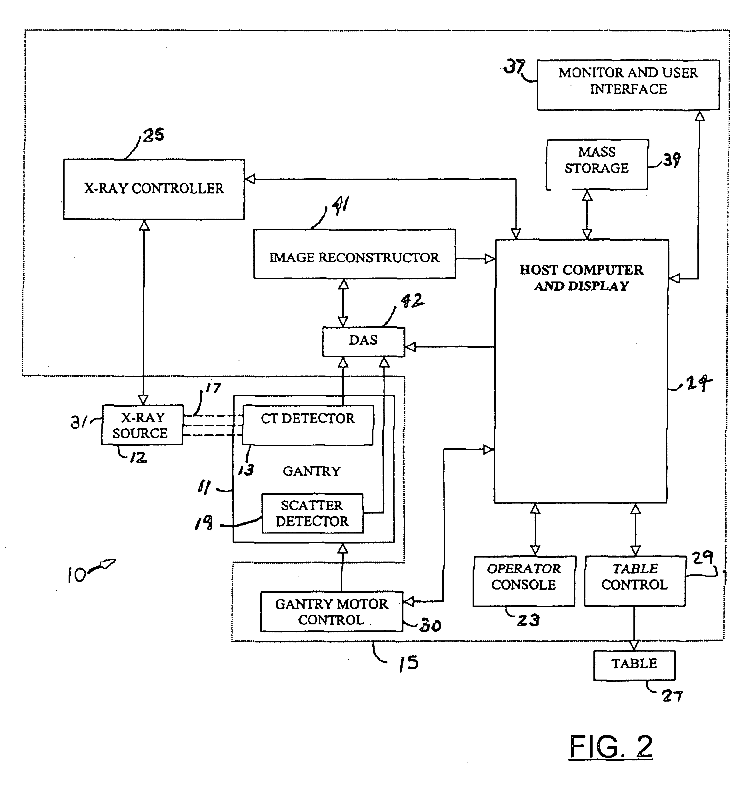
Referring to FIGS. 1 and 2, a CT scanning system 10 including a gantry 11, in accordance with a preferred embodiment of the present invention, is illustrated. An x-ray source 12, coupled to the gantry 11, generates an x-ray flux 17, which passes through an object 18 (e.g. a patient) and produces back-scatter radiation. The system 10 further includes a CT detector 13, coupled to the gantry 11, which generates a detector signal in response to the x-ray flux 17. A first scatter detector 19, generating a scatter signal in response to the scatter radiation, is also coupled to the gantry 11. Position and operation of the scatter detector 19 will be discussed later.

A CT control unit 15, including a host com...


PUM


Abstract

An imaging system includes an x-ray source coupled to a gantry. The x-ray source generates an x-ray flux, wherein a portion of the x-ray flux becomes scatter radiation. A scatter detector is also coupled to the gantry to receive the scatter radiation. The scatter detector generates a scatter signal in response to the scatter radiation, and a host computer receives the scatter signal.

Description

BACKGROUND OF INVENTIONThe present invention relates generally to imaging systems and more particularly to computed tomography. A computed tomography or CT scan is a method of taking pictures of the inside of the body using an ultra-thin x-ray beam. As the x-ray beam passes through the body, it is absorbed by bones, tissues and fluid within the body, thereby varying resultant beam intensity. The intensity of the x-ray beam emerging from the body is measured by a device that converts x-ray beam data into a detailed picture.Multi-slice CT scanners are special CT systems equipped with a multiple-row detector array rather than a single-row detector array. This allows for simultaneous scan of multiple slices at different locations.A typical CT scanner includes a gantry having an annular frame for rotatably supporting an annular disk about a rotation or scanning axis of the scanner. The disk includes a central opening large enough to receive a patient extending along the scanning axis, an...

Claims


Application Information

Patent Timeline
IPC IPC(8): A61B6/02A61B6/03
CPCA61B6/483A61B6/032
Inventor HOFFMAN, DAVID MICHAEL
Owner GE MEDICAL SYST GLOBAL TECH CO LLC
Why Eureka
Try Eureka